Method for controlling engine temperature of an engine

a technology for controlling the temperature of an engine and a control system, which is applied in the direction of electric control, machines/engines, mechanical equipment, etc., can solve the problems of increasing the temperature of the cylinder, increasing the temperature of the engine, and affecting the engine's performance, so as to reduce the displacement of the engine, increase the dynamic range of the engine, and improve the engine's fuel economy

Active Publication Date: 2011-05-05
FORD GLOBAL TECH LLC
View PDF5 Cites 15 Cited by
  • Summary
  • Abstract
  • Description
  • Claims
  • Application Information

AI Technical Summary

Benefits of technology

[0002]Recently, engine fuel economy has been improved by reducing engine displacement and increasing the dynamic range of engines. In particular, smaller engines have been boosted to provide the performance of larger less efficient engines while increasing fuel economy by way of lower engine pumping losses. Further, by directly injecting fuel into a boosted engine, engine performance can be further improved since direct injection of fuel helps to cool the incoming charge, thereby allowing additional air into engine cylinders. However, boosting and directly injecting fuel to cylinders can also cause engine temperature to rise at a rate that is higher than that...

Problems solved by technology

However, boosting and directly injecting fuel to cylinders can also cause engine temperature to rise at a rate that is higher than that of conventionally aspirated engines.
In particular, cylinder temperatures may rise quickly and impart additional heat to the vehicle cooling system since more charge is inducted to cylinders and since downsized engines may have fewer cyli...

Method used


Image

  • Method for controlling engine temperature of an engine
  • Method for controlling engine temperature of an engine
  • Method for controlling engine temperature of an engine

Examples


Embodiment Construction

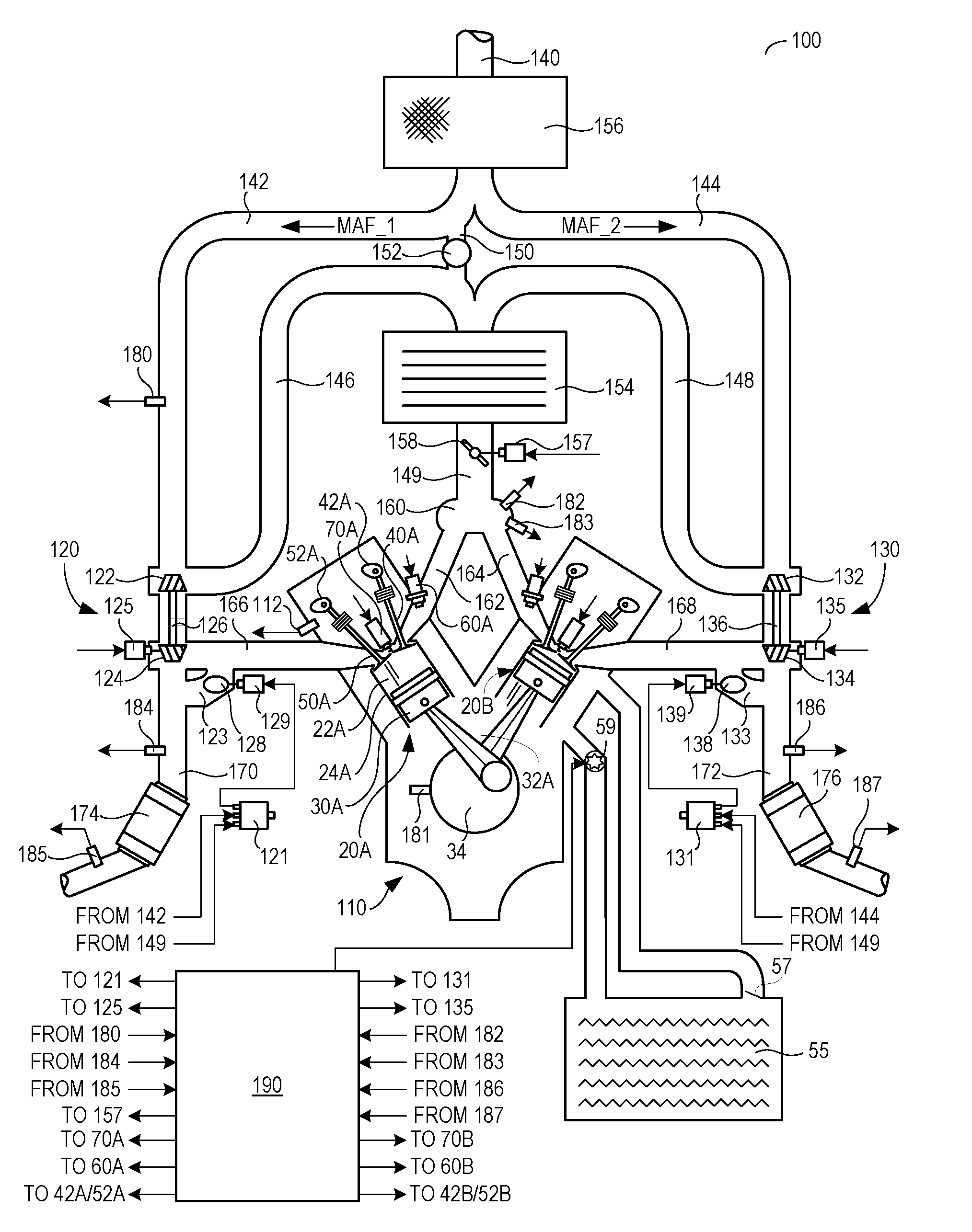
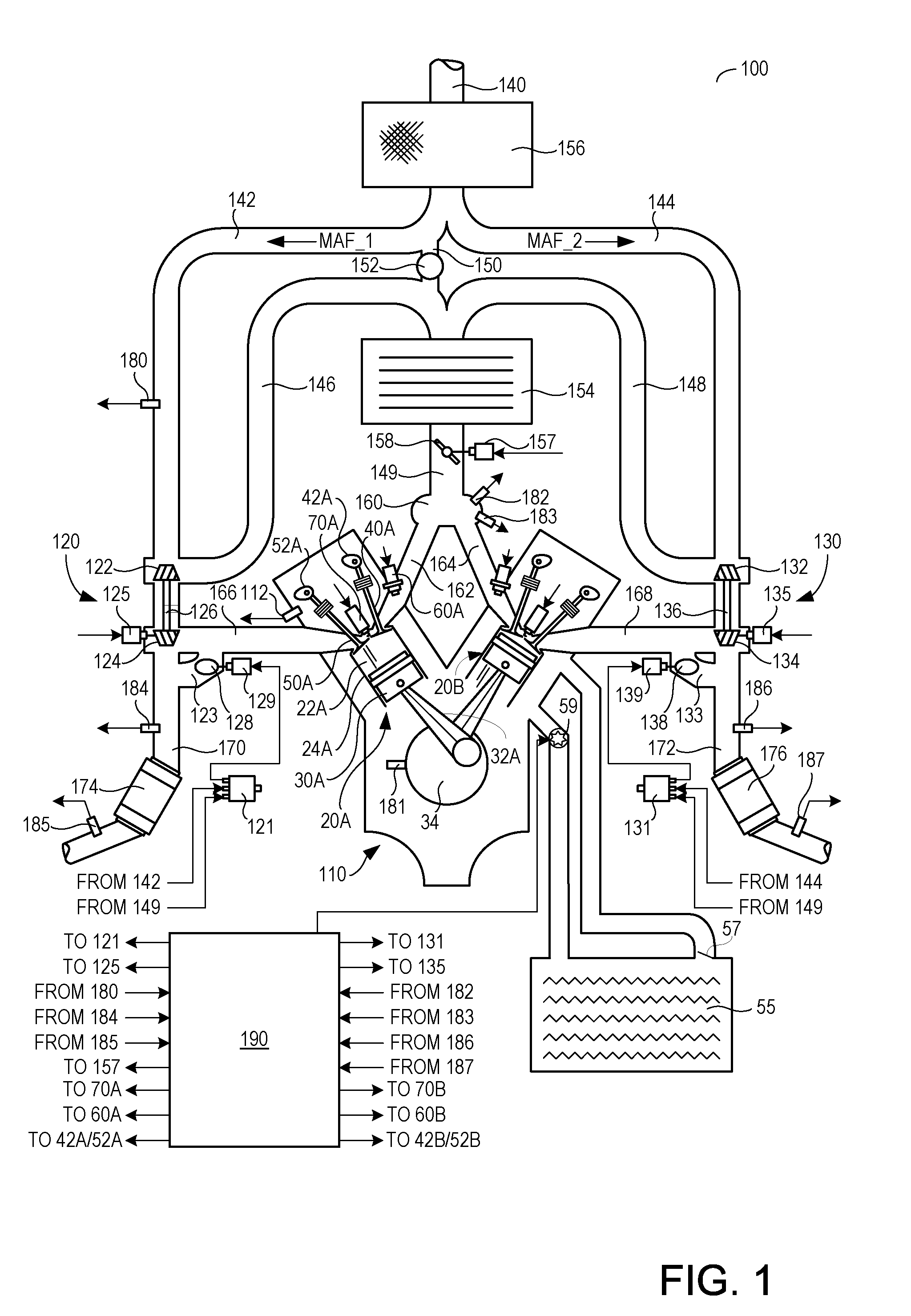
[0012]FIG. 1 shows a schematic depiction of an example engine system 100 including a multi-cylinder internal combustion engine 110 and twin turbochargers 120 and 130. As one non-limiting example, engine system 100 can be included as part of a propulsion system for a passenger vehicle. Engine system 100 can receive intake air via intake passage 140. Intake passage 140 can include an air filter 156. At least a portion of the intake air (MAF_1) can be directed to a compressor 122 of turbocharger 120 via a first branch of the intake passage 140 as indicated at 142 and at least a portion of the intake air (MAF_2) can be directed to a compressor 132 of turbocharger 130 via a second branch of the intake passage 140 as indicated at 144.

[0013]The first portion of the total intake air (MAF_1) can be compressed via compressor 122 where it may be supplied to intake manifold 160 via intake air passage 146. Thus, intake passages 142 and 146 form a first branch of the engine's air intake system. S...


PUM


Abstract

A method for controlling engine temperature of an engine with a wide dynamic range is disclosed. In one example, the derivative of an engine temperature is assessed by a controller. The controller may adjust engine actuators to limit engine temperature in response to the derivative.

Description

TECHNICAL FIELD[0001]The present application relates to the field of automotive engine temperature control systems and methods.BACKGROUND AND SUMMARY[0002]Recently, engine fuel economy has been improved by reducing engine displacement and increasing the dynamic range of engines. In particular, smaller engines have been boosted to provide the performance of larger less efficient engines while increasing fuel economy by way of lower engine pumping losses. Further, by directly injecting fuel into a boosted engine, engine performance can be further improved since direct injection of fuel helps to cool the incoming charge, thereby allowing additional air into engine cylinders. However, boosting and directly injecting fuel to cylinders can also cause engine temperature to rise at a rate that is higher than that of conventionally aspirated engines. In particular, cylinder temperatures may rise quickly and impart additional heat to the vehicle cooling system since more charge is inducted to...

Claims


Application Information

Patent Timeline
IPC IPC(8): F02B33/00F02M7/00F01L1/34
CPCF02D41/0007F02D2041/1432Y10T477/55F02P5/14Y02T10/144F02D2200/021Y02T10/12
Inventor MUKKALA, BENJAMIN CARLSHAW, NATHANAEL DAVIDDEVRIES, JASON EUGENEO'NEIL, BRIAN MICHAELGUINTA, MICHAEL JOSEPH
Owner FORD GLOBAL TECH LLC
Why Eureka
Try Eureka