Instrumented tubing and method for determining a contribution to fluid production

a technology of instrumented tubing and fluid production, which is applied in the direction of fluid removal, survey, borehole/well accessories, etc., can solve the problems of not being able to directly measure the flow contribution of a given zone, sensors have a large investigation depth, and sensors cannot be directly measured. , to achieve the effect of long lifetime function, reliable over time, and cost-effectiveness

Active Publication Date: 2011-05-05
SCHLUMBERGER TECH CORP
View PDF7 Cites 10 Cited by
  • Summary
  • Abstract
  • Description
  • Claims
  • Application Information

AI Technical Summary

Benefits of technology

[0014]The instrumented tubing and method allows scanning the fluid in a small tube rather than the full bore, which is simple, reliable over time and cost effective. They may be used in permanent application while enabling a minimum impact on the well completion. In effect, the instrumented tubing miniaturization and sensors position within the instrumented tubing renders the instrumented tubing suitable for placement in borehole. The instrumented tubing enables long lifetime function according to determined specifications in harsh downhole environments (high pressure and / or temperature, corrosive environment). Further, this solution enables monitoring a larger number of producing zones of a well and improving the metrological performances. In particular, each zone can be isolated and monitored independently which enables determining the contribution of a specific zone to the total produced fluid. Furthermore, when the instrumented tubing is combined with downhole flow control devices, specific zone can be choked and / or in-situ calibration of the sensors can be performed without shutting off all the producing zones.

Problems solved by technology

Such sensors do not allow a direct measurement of the contribution of each zone forming a reservoir.
As a consequence, such sensors have a large investigation depth.
As another consequence, it is not possible to directly measure the flow contribution of a given zone.
Further, in-situ downhole calibrations are difficult to implement and thus rarely applied as they would require shutting off the whole well production.
Such sensors cannot be intrusive, namely protruding inside the well bore because this may hinder or render impossible well interventions.
Such sensors are not adapted to several sizes of wellbore.
Indeed, there isn't a unique sensor design fitting the various configurations encountered downhole.
Therefore, theses sensors are expensive.
As a consequence, the number of zones that can be instrumented is limited.
Such apparatus and method are not adapted for permanent monitoring application of producing hydrocarbon well.

Method used


Image

  • Instrumented tubing and method for determining a contribution to fluid production
  • Instrumented tubing and method for determining a contribution to fluid production
  • Instrumented tubing and method for determining a contribution to fluid production

Examples


Embodiment Construction

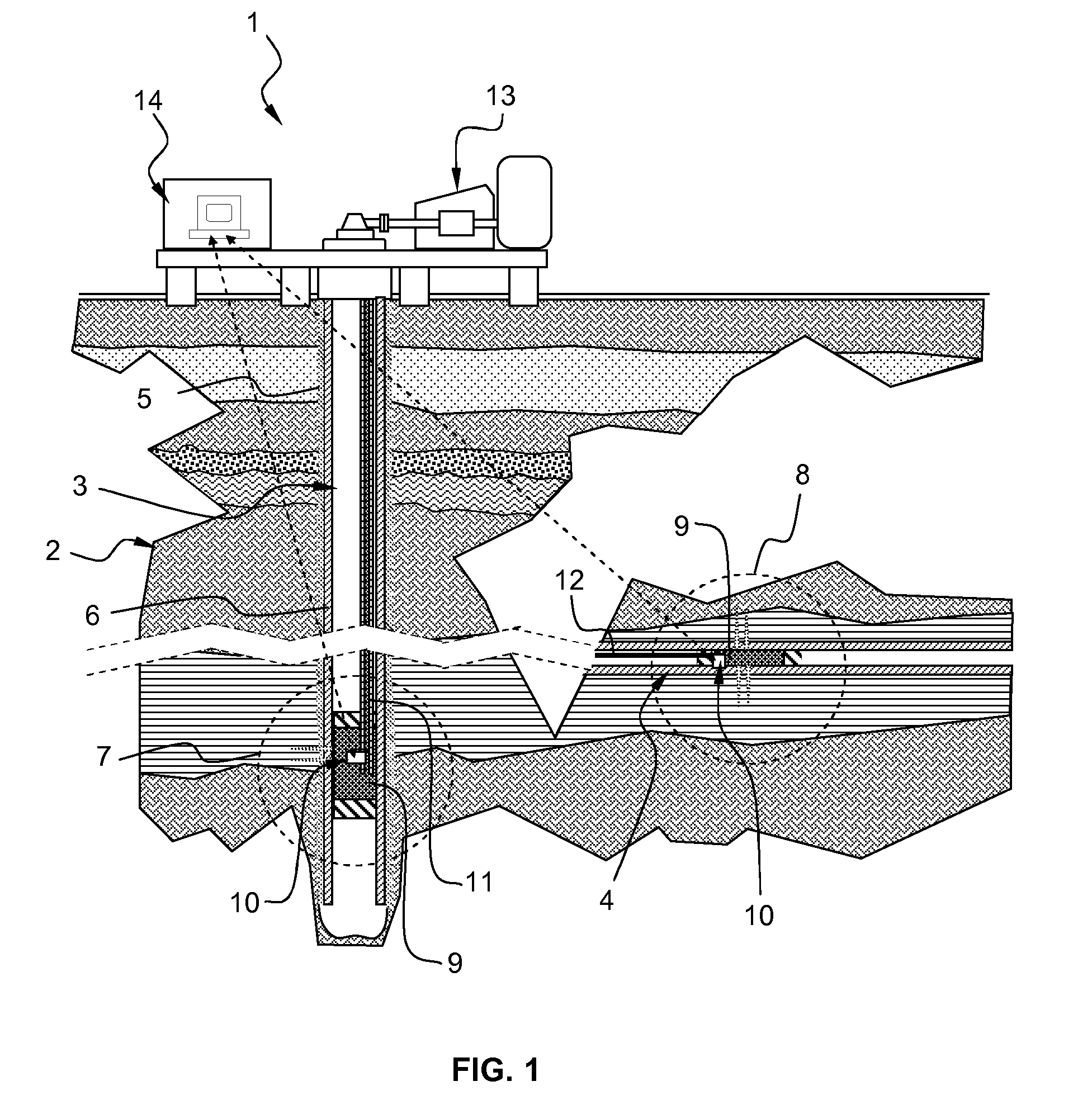
[0021]FIG. 1 schematically shows an onshore hydrocarbon well location and equipments 1 above a hydrocarbon geological formation 2 after drilling operation has been carried out, after a drill pipe has been run, and after cementing, completion and perforation operations have been carried out. The well is beginning producing hydrocarbon, e.g. oil and / or gas. At this stage, the well bore comprises substantially vertical portion 3 and may also comprise horizontal or deviated portion 4. The well bore 3, 4 is either an uncased borehole, or a cased borehole comprising a casing 5 and an annulus 6, or a mix of uncased and cased portions.

[0022]The annulus 6 may be filled with cement or an open-hole completion material, for example gravel pack. Downhole, a first 7 and second 8 producing sections of the well typically comprises perforations, production packers and production tubing at a depth corresponding to a reservoir, namely hydrocarbon-bearing zones of the hydrocarbon geological formation 2...


PUM


Abstract

An instrumented tubing for determining a contribution of a given zone to fluid production of a reservoir, the instrumented tubing including a tube having an open end for collecting a fluid flowing from the given zone and a port for coupling the tube to a production tubing for letting the collected fluid flow into the production tubing, and a sensor for measuring a parameter of the collected fluid, wherein the sensor is connected to an electronic unit for determining the contribution of the given zone to the fluid production of the reservoir based on said measured parameter.

Description

FIELD[0001]An aspect of the disclosure relates to an instrumented tubing and / or a method for determining a contribution of a given zone to fluid production of a reservoir, and in particular but not exclusively, of a hydrocarbon fluid mixture flowing from a given zone of a reservoir in a borehole of a producing hydrocarbon well.BACKGROUND[0002]During completion operations, the completion / production equipments like packers, production tubings, valves, various sensors or measuring apparatuses, etc. . . . are installed downhole. Subsequently, production operations can begin. It is known to deploy permanent sensors for measuring various parameter related to the reservoir, the borehole, the fluid flowing into the borehole, etc. . . . These sensors are used to monitor the downhole reservoir zones and control the production of hydrocarbon. Such monitoring of the production enables enhancing hydrocarbon recovery factor from reservoir by taking appropriate action, for example by isolating a z...

Claims


Application Information

Patent Timeline
Patent Type & Authority Applications(United States)
IPC IPC(8): E21B34/06E21B43/00E21B34/00E21B47/10
CPCE21B47/10
Inventor CENS, FABIENDUFOUR, YANNCHOUZENOUX, CHRISTIAN
Owner SCHLUMBERGER TECH CORP
Why Eureka
Try Eureka