Brake Disc and Disc Brake

Active Publication Date: 2011-05-05
LUCAS AUTOMOTIVE GMBH
View PDF14 Cites 4 Cited by
  • Summary
  • Abstract
  • Description
  • Claims
  • Application Information

AI Technical Summary

Benefits of technology

[0021]The underlying feature of the invention is to provide a brake disc and a disc brake, with which undesirable thermal and acoustic effects are extensively avoided.
[0024]One possibility of configuring the transitions between the supporting elements and the plates forming the friction paths in the above sense is to make the radii of curvature of the transitions between the supporting elements and the plates on the one side of the brake disc differ from those on the other side of the brake disc. Larger radii of curvature bring about a greater transfer of heat.
[0025]The previously described inventive idea may be applied also to brake discs having air-swept hollows that are formed, not by free spaces between supporting elements, but for example by air-swept spiral channels, radially extending cavities etc. With such developments of the hollows it is also possible by means of the described asymmetrical configuration of the wall geometry on both sides of the brake disc to achieve the effect of as homogeneous a temperature distribution as possible in the brake.
[0026]According to another development of the invention the homogeneous temperature distribution in the brake disc is promoted by disposing the hollows swept by cooling air, not precisely centrally in the brake disc, but with an axial offset (in relation to the axis of the brake disc) such that the side of the brake disc that without this offset would be heated to a greater extent consequently has the same temperature as, or as similar as possible a temperature to, the other side of the brake disc, on which without the offset of the hollows there would be a greater removal of heat. By means of the different configuration according to the invention of the transition regions between the supporting elements and the plates on both sides of the brake the previously described “offset” of the hollows in relation to the centre plane of the brake disc may be kept relatively slight, with the result that the regrettable risks of the prior art with regard to disc cracks in the case of different friction path thicknesses (i.e. different strengths of the said plates) may be reduced.
[0028]The invention makes it possible to homogenize the heat distribution in the friction threads and in the brake disc without a significant weight increase.

Problems solved by technology

Nevertheless considerable heating of the brake disc occurs during more extreme and / or extended braking operations.
Rather, temperature gradients arise and may lead to deformation of the brake disc, in particular to the known so-called umbrella effect, i.e. an arching of the brake disc.
Such deformations are highly undesirable.
A further problem that repeatedly has to be solved with disc brakes is so-called brake squeal, which may occur i.e. also because various vibration effects may arise through reciprocal action (coupling) in the brake.
This may lead at specific brake forces to a resonant coupling and hence to extremely undesirable squealing noises.
The intention here is to shift the natural frequencies and in particular the axial bending modes towards higher frequencies, thereby making a vibration coupling with other sub-systems of the brake difficult.
The intention here is that cracks due to thermal stress may occur only after a very long operating period and very extraordinary stresses.
The uniform thermal load is also to lead to uniform wear of the brake linings.

Method used


Image

  • Brake Disc and Disc Brake
  • Brake Disc and Disc Brake
  • Brake Disc and Disc Brake

Examples


Embodiment Construction

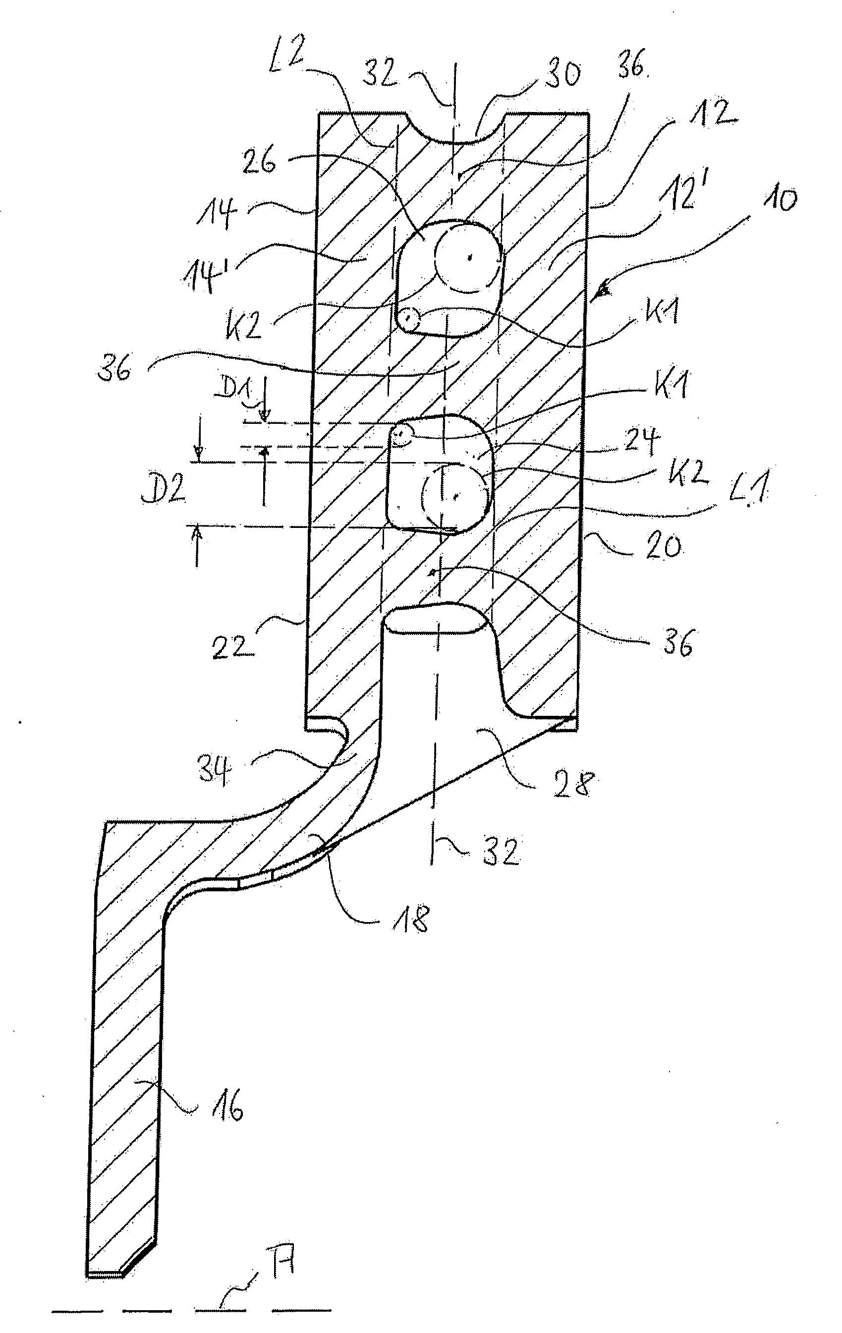
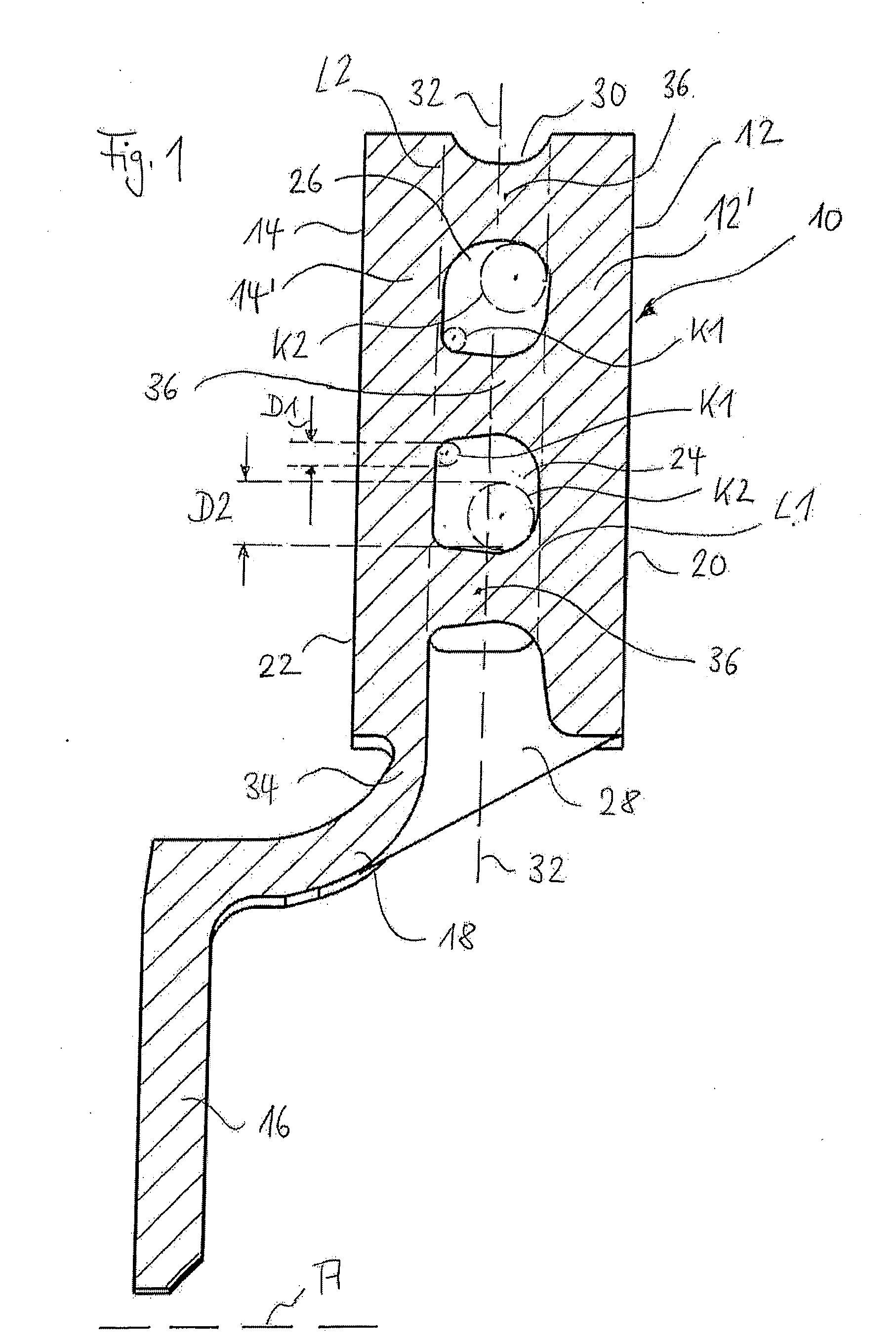
[0038]The figures show parts of a disc brake that are relevant in the context of the invention, namely the brake disc. The other components of the disc brake, such as the brake anchor plate, the caliper etc., may be gathered from the various developments according to the prior art.

[0039]Of the brake disc 10, the section along a radius is shown in FIG. 1. The brake disc therefore rotates about its axis A.

[0040]The brake disc 10 has an inner friction path 12 and an outer friction path 14. The inner friction path 12 is formed by an (inner) plate 12′ and the outer friction path 14 is formed by an (outer) plate 14′. The brake disc in an, as such, known manner has a brake disc pot 16, by which the fastening to the vehicle part to be braked is effected. This is generally the wheel hub. In vehicles, in which the brake is disposed on the differential gear, the brake disc is connected to a part of the axle drive.

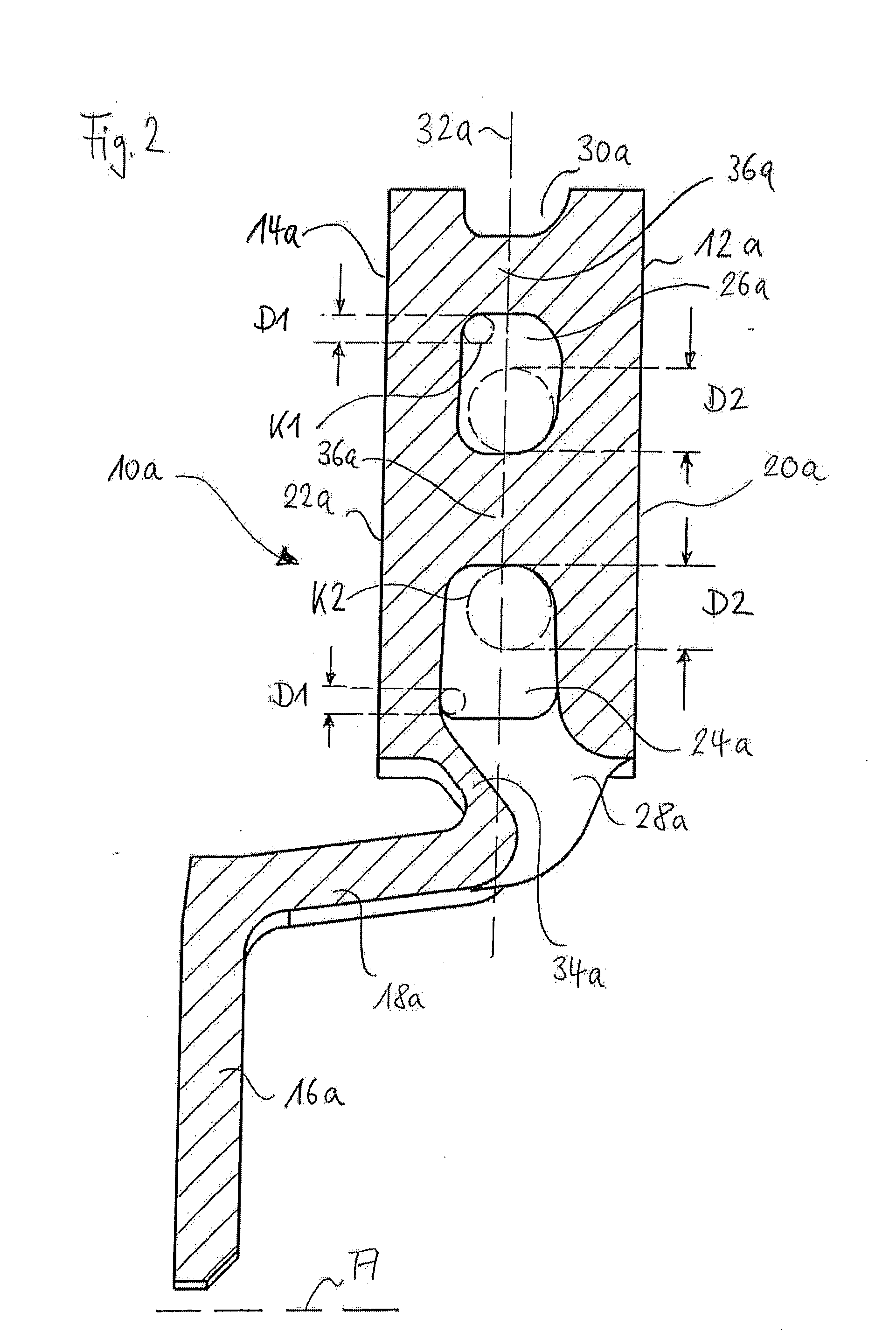
[0041]The ventilated brake disc 10 is configured for fastening to a wheel hub. Ex...


PUM


Abstract

A brake disc has an outer friction path on one side and an inner friction path on the other side. Between the friction paths free spaces are provided, which on the outer friction path side have a different configuration than on the inner friction path side.

Description

CROSS-REFERENCE TO RELATED APPLICATIONS[0001]This application is a national stage of International Application No. PCT / EP2009 / 002384 filed Apr. 1, 2009, the disclosures of which are incorporated herein by reference in entirety, and which claimed priority to European Patent Application No. 08 006 702.8 filed Apr. 1, 2008, the disclosures of which are incorporated herein by reference in entirety.BACKGROUND OF THE INVENTION[0002]The invention relates to a brake disc for a disc brake, having an outer friction path on one side and an inner friction path on the other side of the brake disc and having air-swept hollows (recesses) between the friction paths for cooling the brake disc, as well as to a disc brake, in which such a brake disc is fitted, the brake disc therefore being a so-called ventilated brake disc.[0003]Such brake discs are known from DE 10 2007 010 487 A1.[0004]In physical terms, the braking operation in a motor vehicle means that its kinetic energy is converted substantial...

Claims


Application Information

Patent Timeline
IPC IPC(8): F16D65/847F16D65/12
CPCF16D65/128F16D2065/1328F16D65/847
Inventor SEUSER, ULRICHRYCHLIK, MICHAELSEYHUN, SERDARKORTE, JURGEN
Owner LUCAS AUTOMOTIVE GMBH
Why Eureka
Try Eureka