Digital radar or sonar apparatus

a digital radar and sonar technology, applied in the field of digital radar or sonar equipment, can solve the problems of radar signal processors, size, weight and power constraints, and the inability of each display apparatus to connect, and achieve the effect of analog processing and control

Active Publication Date: 2011-05-05
FLIR BELGIUM BVBA
View PDF72 Cites 20 Cited by
  • Summary
  • Abstract
  • Description
  • Claims
  • Application Information

AI Technical Summary

Benefits of technology

[0049]A media access controller (MAC) in a component such as an electronic integrated circuit or functional block of a circuit that provides addressing and access control mechanisms that makes it possible for several network nodes to communicate within a multipoint communications network.
[0061]Moreover, the use of multiple look-up tables, or a look-up table with multiple table regions, also permits updating. Thus, when data in one table or table region is being used, data in another table or table region may be up dated without affecting the current operation of the apparatus.
[0064]With the present invention it is possible to produce a scanner with improved display of pulse radar or sonar data. The invention may make use of multi-bit digital signal processing with linear conversion to baseband. If digital control is used, this enables the scanner to combat the effects of temperature and ageing that affect analog circuitry.

Problems solved by technology

Any signal processing that takes place in such displays is limited by the thresholding that take place in the comparator.
This is because there are size, weight and power constraints on the radar scanner enclosure.
When multiple displays are used, the radar information is typically sent out over a network, the radar signal processors, in the each display apparatus not connected directly to the scanner, are idle and redundant.
When a large number of different pulse-widths (say 8) are available, providing matched analog filtering becomes onerous to set-up, and liable to drift.
The poor removal of these spurious products causes aliasing, and destroys information that could have been used in later signal processing, for enhancing the quality of the displayed information.
These have been expensive and difficult to use.
Thus linear detection and processing have not previously been considered, being both uneconomic and unreliable (due to high power dissipation).
The displays from each range have the disadvantage of clearly not being simultaneously updated, which creates an ambiguity.
There is a resulting loss of information.
However, in the arrangement shown in FIG. 1, all but one of those multiple display structures is mostly redundant.

Method used


Image

  • Digital radar or sonar apparatus
  • Digital radar or sonar apparatus
  • Digital radar or sonar apparatus

Examples


Embodiment Construction

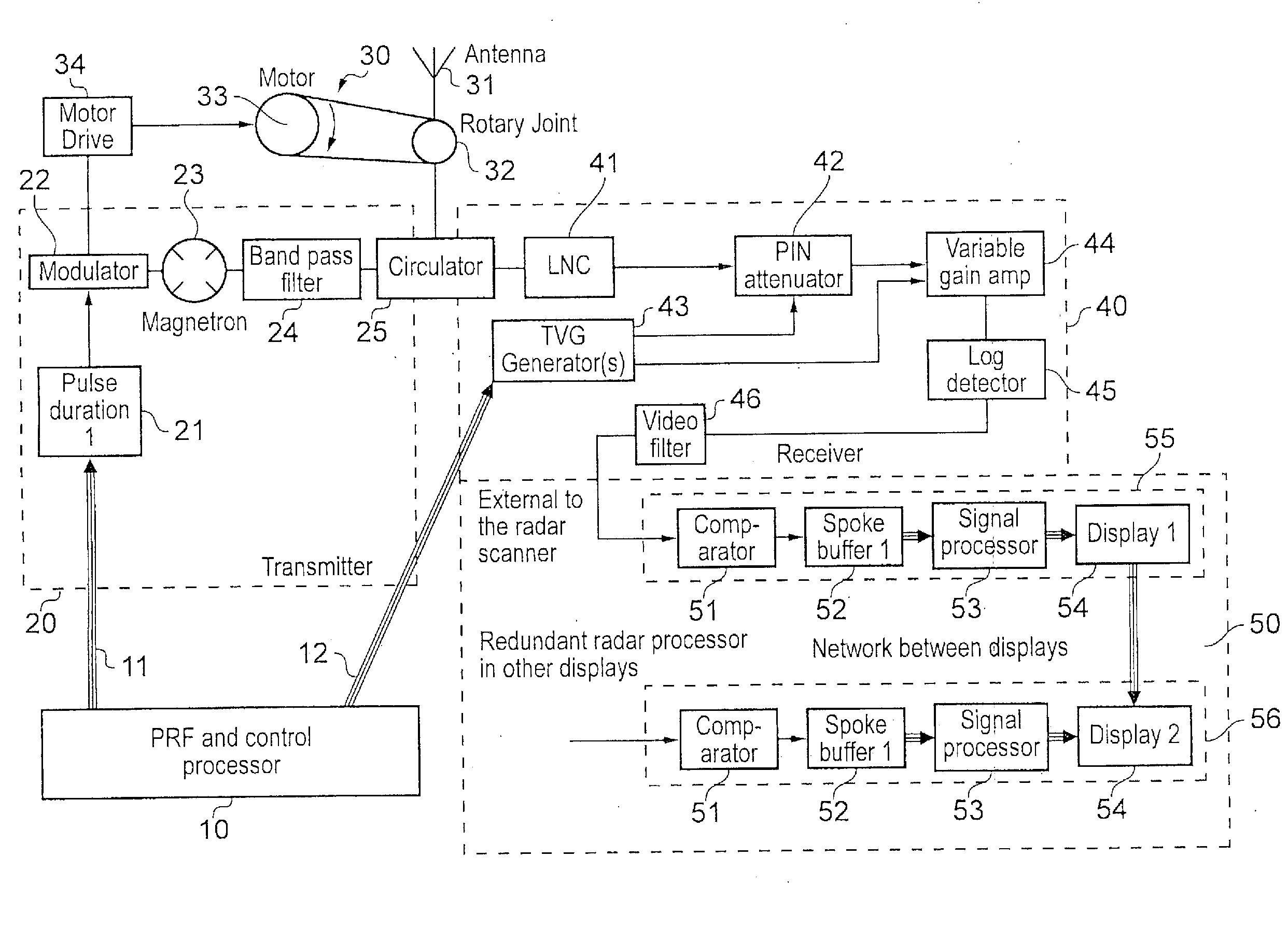
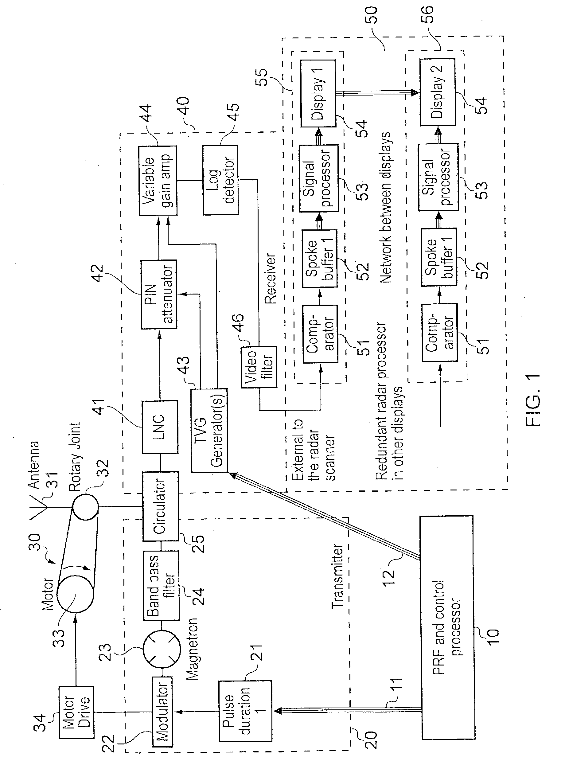
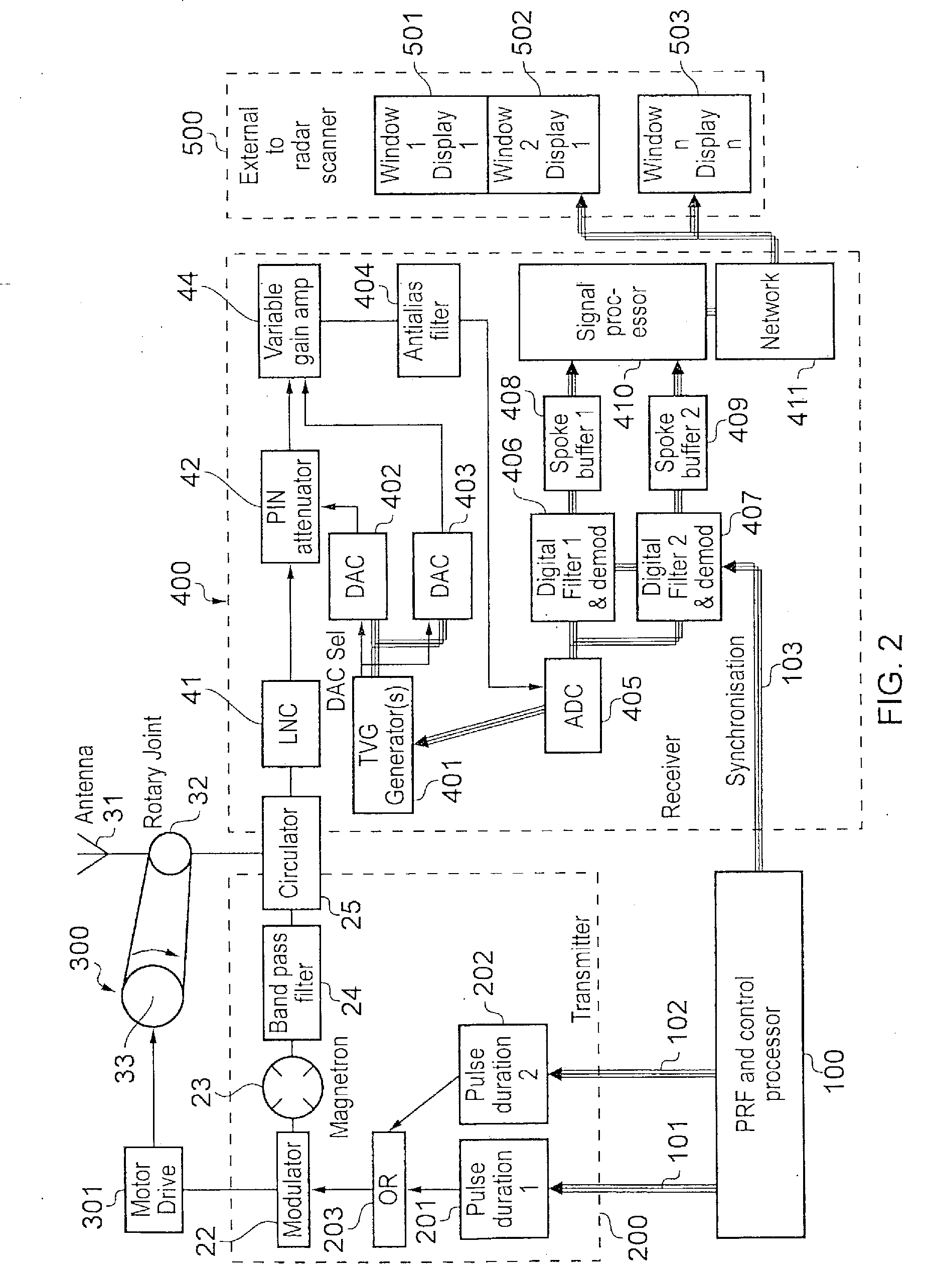
[0078]A radar apparatus embodying the various aspects of the invention will now be described in detail. FIG. 2 shows the general structure of the apparatus of this embodiment. As in the known arrangement of FIG. 1, the apparatus comprises five components, namely a control processor 100, a transmitter section 200, an antenna section 300, a receiver section 400, and a display section 500. Some of the sub-components of the transmitter section 200, antenna section 300, and receiver section 400 correspond to components of the transmitter section 20, the antenna section 30 and the receiver section 40 of the arrangement of FIG. 1, and the same reference numerals will be used for corresponding parts.

[0079]However, the apparatus of FIG. 2 is intended to generate multiple displays at different radar ranges. Thus, the control processor 100 generates two types of pulse repetition frequency signals which are transmitted via separate digital buses 101, 102 to separate pulse duration units 201, 20...


PUM


Abstract

A radar or sonar system amplifies the signal received by an antenna of the radar system or a transducer of the sonar system is amplified and then subject to linear demodulation by a linear receiver. There may be an anti-aliasing filter and an analog-to-digital converter between the amplifier and the linear receiver. The system may also have a digital signal processor with a network stack running in the processor. That processor may also have a network interface media access controller, where the system operates at different ranges, the modulator may produce pulses of two pulse patterns differing in pulse duration and inter-pulse spacing, those pulse patterns are introduced and used to form two radar images with the two images being derived from data acquired in a duration not more than twenty times larger than the larger inter-pulse spacing, or for a radar system, larger than one half of the antenna resolution time. One or more look-up tables may be used to control the amplifier. The radar system may generate digital output which comprises greater than eight levels of radar video.

Description

BACKGROUND OF THE INVENTION[0001]1. Field of the Invention[0002]The present invention relates to a radar or sonar apparatus. It is particularly concerned with such an apparatus including digital processing of the radar or sonar signals received[0003]2. Summary of the Prior Art[0004]Radar scanners have been manufactured since the 1940's. The development of radar has diverged into two methods, non-coherent pulse radars and Doppler radars. Doppler radars have received considerable development for military and aviation use. Modern Doppler radars make extensive use of digital signal processing and digital control. However pulse radars have remained extensively analog, using logarithmic receivers and analog gain controls to generate baseband video that is sent to the display for processing. The display converts the baseband video to digital form using a 1-bit comparator. Any signal processing that takes place in such displays is limited by the thresholding that take place in the comparato...

Claims


Application Information

Patent Timeline
Patent Type & Authority Applications(United States)
IPC IPC(8): G01S13/32
CPCG01S7/062G01S7/285G01S7/34G01S7/526G01S7/529G01S7/292G01S13/106G01S13/89G01S15/102G01S15/89G01S7/62G01S7/282G01S7/5273G01S7/6263G01S13/10
Inventor JALES, RICHARDLAWRENCE, ADREWMAINDROU, MATTHIEU
Owner FLIR BELGIUM BVBA
Why Eureka
Try Eureka