Methods and apparatus for providing touch sensitive displays

a touch-sensitive display and touch-sensitive technology, applied in the direction of static indicating devices, instruments, paper/cardboard containers, etc., can solve the problems of reducing the transparency of glass, few practical manufacturing processes available for cutting such glass, and affecting the cost of the approach

Inactive Publication Date: 2011-05-05
CORNING INC
View PDF12 Cites 121 Cited by
  • Summary
  • Abstract
  • Description
  • Claims
  • Application Information

AI Technical Summary

Benefits of technology

It has been discovered that commercial advantages may be obtained when the construction of the touch sensitive display 10 is thinner and lighter. This may be achieved when the touch glass 14 is eliminated and the functionality thereof is integrated into the cover glass 16, e.g., by placing the electrical traces 18, 20 on an inside surface of the cover glass 16. If the cover glass 16 were not hardened, a manufacturing approach would be to start with a single, large glass panel (large enough for many touch sensitive displays), pattern the panel with electrical traces 18, 20 using photolithography, and then singulating (cutting) the larger panel into smaller, individually-sized touch sensitive displays.

Problems solved by technology

A compromise has to be reached during film deposition on the touch glass 14, however, as increasing the concentration of charge carriers in the material will increase the conductivity, but decrease its transparency.
In some applications, such as when using chemically strengthened glass (e.g., ion exchanged, alkali aluminosilicate glass), there are few practical manufacturing processes available for cutting such glass after it has been hardened.
This approach has a significant cost impact as small, singulated panels do not lend themselves to large scale, and cost-effective, photolithography.

Method used


Image

  • Methods and apparatus for providing touch sensitive displays
  • Methods and apparatus for providing touch sensitive displays
  • Methods and apparatus for providing touch sensitive displays

Examples


Embodiment Construction

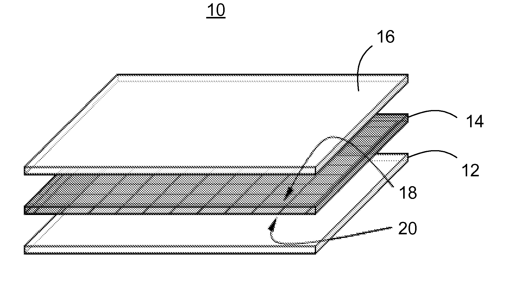
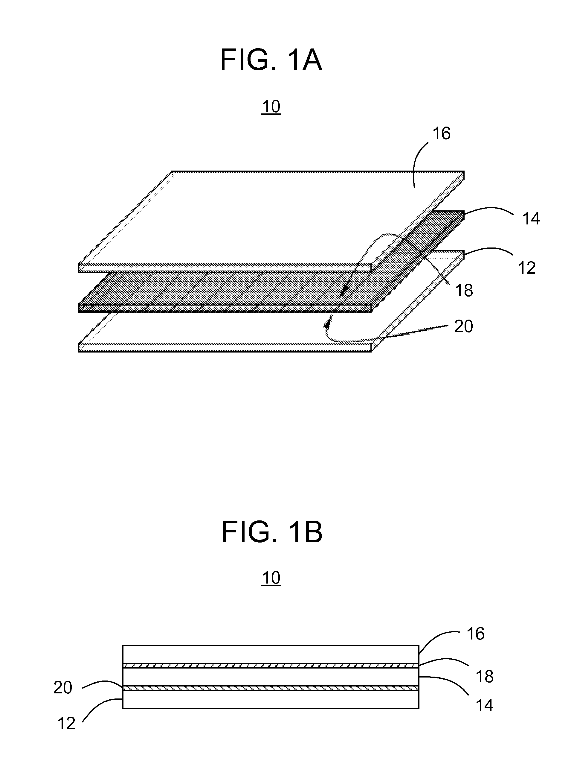
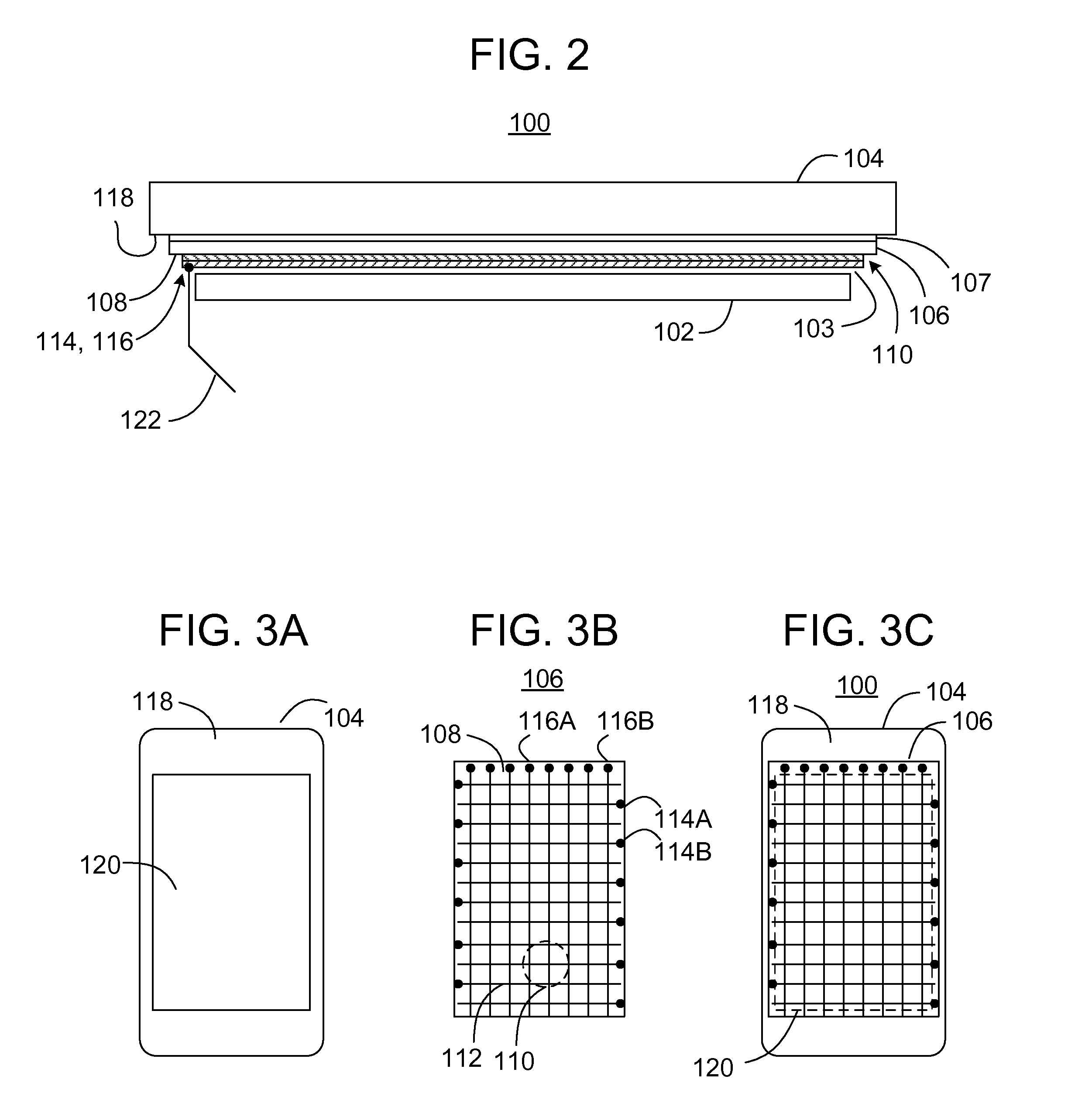
With reference to the drawings wherein like numerals indicate like elements there is shown in FIG. 2 a touch sensitive display 100 in accordance with one or more embodiments and aspects described herein. The touch sensitive display 100 may be used in a variety of consumer electronic articles, for example, cell-phones and other electronic devices capable of wireless communication, music players, notebook computers, mobile devices, game controllers, computer “mice”, electronic book readers and other devices.

The touch sensitive display 100 includes a display layer 102, a cover glass layer 104, and a touch glass layer 106 positioned between the display layer 102 and the cover glass layer 104. The touch sensitive display 100 may include an air gap 103 between the display layer 102 and the touch glass 106 and grid 110 combination. The touch glass 106 and grid 110 combination may be laminated to the cover glass layer 104 via an adhesive layer 107.

The touch glass layer 106 includes a first ...


PUM

PropertyMeasurementUnit
widthaaaaaaaaaa
thickaaaaaaaaaa
thicknessaaaaaaaaaa

Abstract

Methods and apparatus provide for a touch sensitive display, which may include: a display layer; a cover glass layer formed from ion exchanged glass; and an optional touch glass layer, where, either on a first side of the touch glass or on a first side of the cover glass, a grid of electrode traces is disposed, which is sensitive to distortions of a local electrostatic field caused by a touching event, and the grid may be positioned between the display layer and the cover glass layer.

Description

BACKGROUND OF THE INVENTIONThe present invention relates to methods and apparatus for providing touch sensitive displays, such as liquid crystal displays, organic light emitting diode displays, etc.The display market is eager for displays that offer touch sensing capability—and the market size for displays with touch functionality is expected to grow tremendously in the coming years. As a result, many companies have researched a variety of sensing techniques, including resistive, projected capacitive, infrared, etc. While many of these techniques result in reasonable touch capability, each technique carries some performance disadvantage for specific applications, and nearly all result in significant added cost to the manufacture of each display.In terms of performance, the basic metrics for touch sensitive displays are the accurate sensing of a touch event and the determination of the precise location of the touch event on the touch / display window. Many secondary attributes are beco...

Claims


Application Information

Patent Timeline
Patent Type & Authority Applications(United States)
IPC IPC(8): G06F3/041C03C21/00B32B37/14B32B38/00B32B38/10B32B38/14
CPCG06F3/044Y10T156/1052Y10T156/10Y10T156/1075G06F3/0443G06F3/0446G06F3/047G09G2300/04
Inventor ORSLEY, TIMOTHY J.TROTT, GARY R.
Owner CORNING INC
Why Eureka
Try Eureka