Low Power Driving Method for a Display Panel and Driving Circuit Therefor

a technology of low power driving and display panel, which is applied in the direction of electric digital data processing, instruments, computing, etc., can solve the problems of degrading performance, increasing power consumption and transition time, and reducing so as to achieve power saving and efficient reduction of the voltage range of the data lin

Inactive Publication Date: 2011-05-05
RAYDIUM SEMICON
View PDF3 Cites 13 Cited by
  • Summary
  • Abstract
  • Description
  • Claims
  • Application Information

AI Technical Summary

Benefits of technology

[0008]The invention is directed to a driving method for display panel and a device therefor. According to an embodiment of the invention, the corresponding data code of the grey level to be displayed by the pixel is utilized to predict a trend of the corresponding target voltage of the data line, and according to the prediction result, the voltage of the data line is changed to a voltage close to the target voltage. Thus, the swing range of the voltage of the data line can be efficiently reduced, and power saving and reduction in transition time can also be achieved.

Problems solved by technology

However, the above conventional driving method may even increase power consumption under certain circumstances.
As disclosed above, under many circumstances, the conventional driving method does not narrow the swing range of the source line and may even increase power consumption and the transition time instead, thus degrading its performance.

Method used


Image

  • Low Power Driving Method for a Display Panel and Driving Circuit Therefor
  • Low Power Driving Method for a Display Panel and Driving Circuit Therefor
  • Low Power Driving Method for a Display Panel and Driving Circuit Therefor

Examples


first embodiment

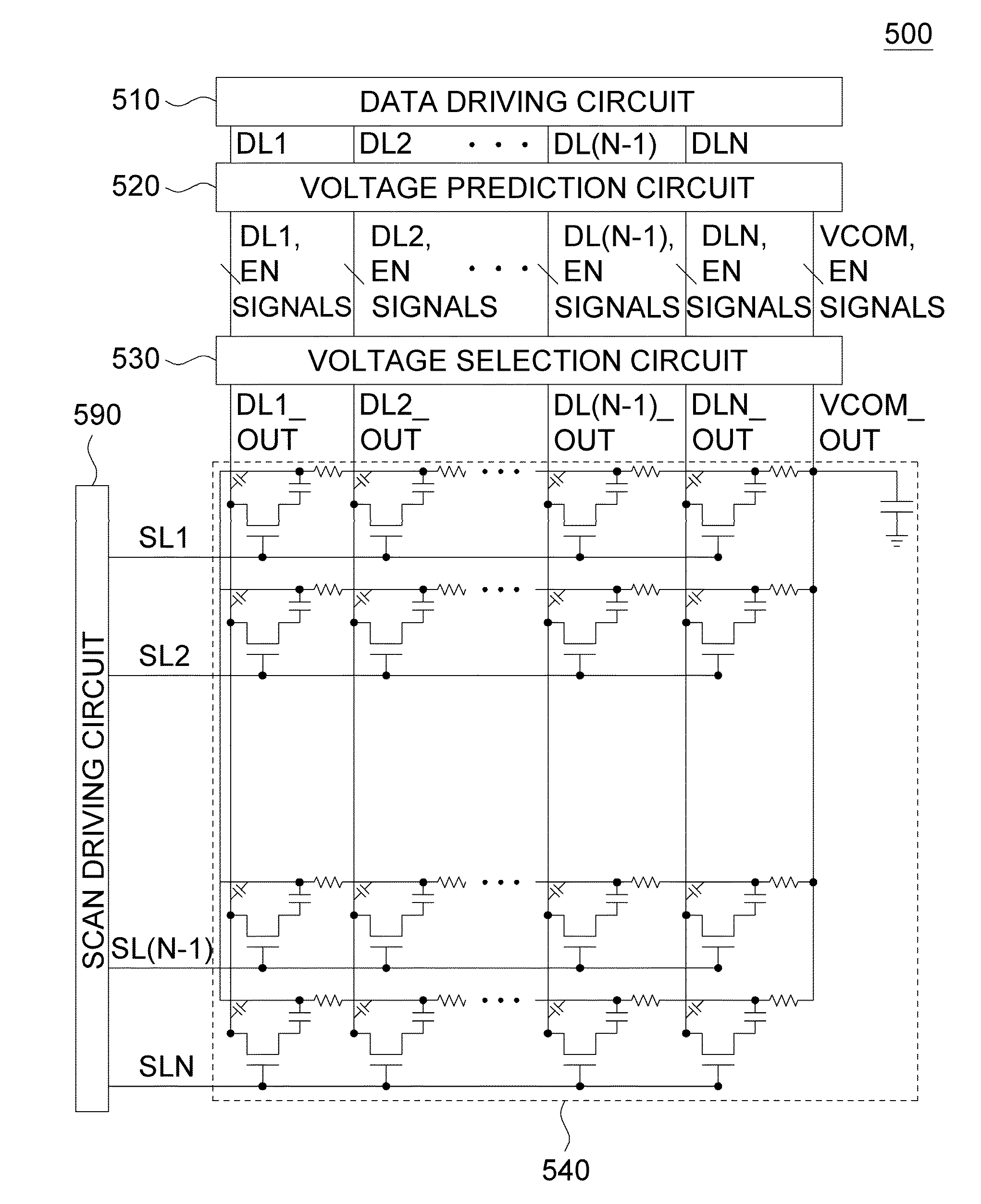
[0019]According to a driving method of the first embodiment of the invention, the voltage of a corresponding pixel electrode of a pixel is driven when the voltage of the corresponding common electrode of the pixel in a pixel array is changing from one of a first common voltage (Vcom1) and a second common voltage (Vcom2) to the other thereof according to a polarity signal. The driving step includes at least two sub-steps:

[0020](a) Within a time interval, the voltage of the pixel electrode of the pixel is changed to one of a plurality of voltage levels, such as one of a first voltage (V1) and a second voltage (V2), selectively according to a data code for the pixel and the polarity signal, so that the voltage of the pixel electrode becomes closer to a corresponding target voltage of the data code. (b) After the time interval, the data line, whose voltage has been changed, is enabled to receive a target voltage so as to generate a desired voltage difference between the data line and th...

second embodiment

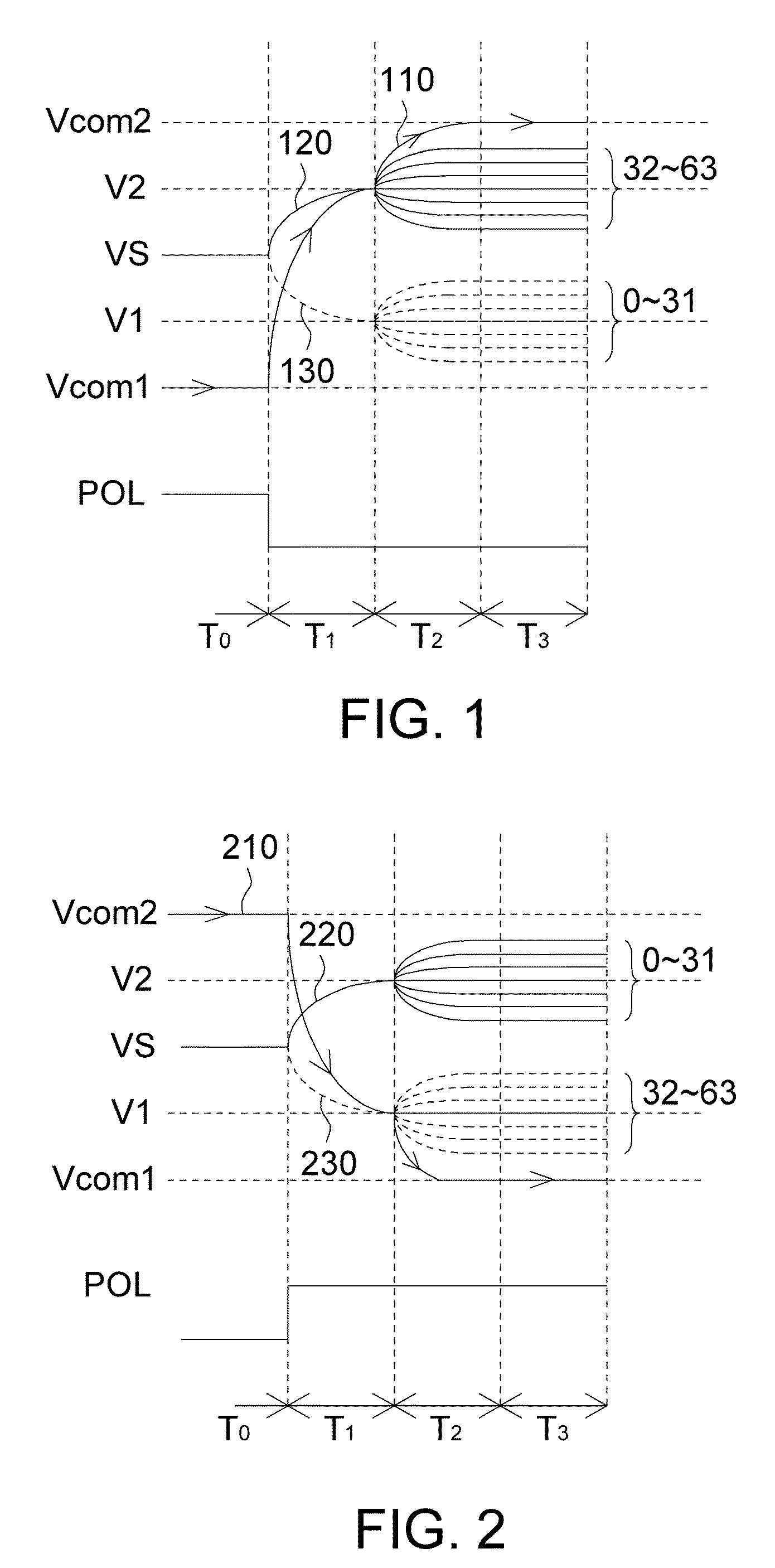
[0025]The sub-step (a) of the first embodiment makes the voltage of the pixel electrode closer to the corresponding target voltage of the data code. Based on the first embodiment, the sub-step (a) of the second embodiment appropriately changes the voltage of the pixel electrode to be closer to the corresponding target voltage of the data code through pre-charging method and the determination result in the prediction of the trend of the target voltage.

[0026]FIGS. 1 and 2 respectively show a schematic diagram of a driving method according to the second embodiment of the invention. In FIG. 1, when the polarity signal POL indicates that the common voltage is changed from positive polarity to negative polarity, as indicated by an upward curve 110 with an arrow, the common voltage is changing from a first common voltage Vcom1 to a second common voltage Vcom2, the voltage of the pixel electrode VS of a pixel is driven. In FIG. 2, when the polarity signal POL indicates that the common volta...

third embodiment

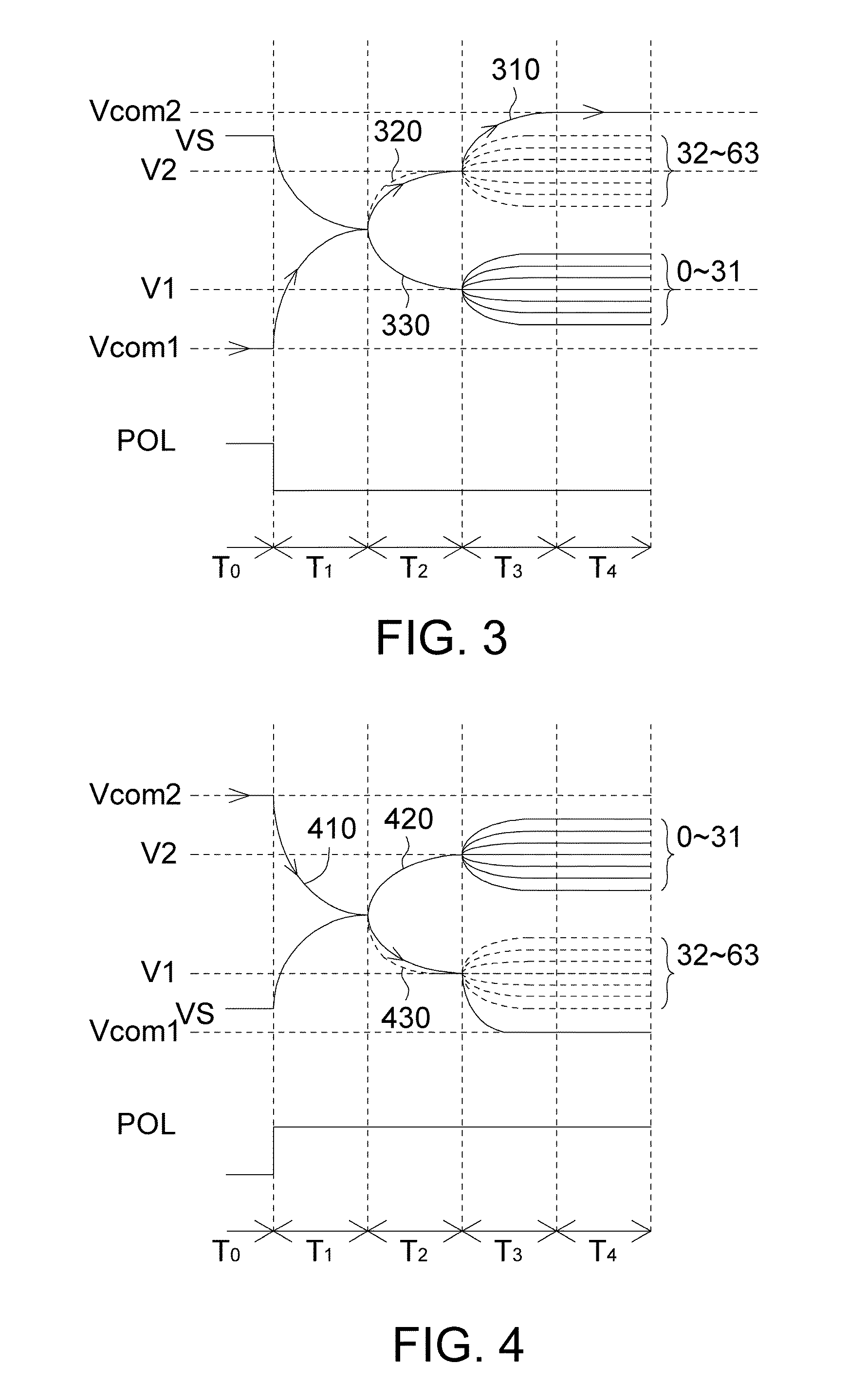
[0038]Referring to FIGS. 3 and 4, a schematic diagram of a driving method according to the third embodiment of the invention is respectively shown. The driving method of the third embodiment can be based on any of the above embodiments. Besides, the step of driving the voltage of a corresponding pixel electrode of a pixel further includes: within a time interval (e.g., the time interval T1 of FIG. 3 or 4), connecting the common electrode and the pixel electrode of a pixel, or making the two electrodes short-circuited, so that the voltages of the two electrodes achieve a balance voltage. Afterwards, the step of making the voltage of the pixel electrode even closer to the corresponding target voltage of the data code is performed. In this manner, better performance in power saving and reduction in transition time can be achieved since the connecting method leads to charge redistribution by way of charge sharing.

[0039]The step of making the voltage of the pixel electrode even closer to...


PUM


Abstract

A low power driving method for a display panel and a driving circuit therefor. When the voltage of a corresponding common electrode of a pixel in a pixel array is changed from one of the first voltage and the second voltage to the other thereof according to a polarity signal, the voltage of the corresponding pixel electrode of the pixel is driven. In an embodiment, a data code for the pixel and the polarity signal are utilized to predict a trend of the corresponding target voltage of the data code, and the voltage of the pixel electrode or the data line is changed to a voltage close to the target voltage of the pixel according to the prediction result. Thus, the swing range of the voltage of the data line can be efficiently reduced, and power saving and reduction in transition time can also be achieved.

Description

[0001]This application claims the benefit of Taiwan application Serial No. 98128641, filed Aug. 26, 2009, the subject matter of which is incorporated herein by reference.BACKGROUND OF THE INVENTION[0002]1. Field of the Invention[0003]The invention relates in general to a driving method for display panel and a driving circuit therefor, and more particularly to a low power driving method for a display panel and a driving circuit therefor.[0004]2. Description of the Related Art[0005]The generally known method for driving a panel achieves power saving and reduction in transition time by way of pre-charging. According to the method disclosed in U.S. Pat. No. 7,362,293, during consecutive scan periods, the common voltage Vcom of a common electrode is continually changed by way of line inversion driving method, and the swing range of the source line and the common electrode are narrowed by way of pre-charging.[0006]However, the above conventional driving method may even increase power cons...

Claims


Application Information

Patent Timeline
Patent Type & Authority Applications(United States)
IPC IPC(8): G09G5/00
CPCG09G2230/00G09G2320/0252G09G3/3648G09G3/3614
Inventor HOU, CHUN-LIN
Owner RAYDIUM SEMICON
Why Eureka
Try Eureka