Static var compensator with multilevel converter

A compensator and converter technology, applied in reactive power compensation, reactive power adjustment/elimination/compensation, active power filtering, etc., can solve problems such as pre-assembly, testing and transportation difficulties, and minimize weight and cost , low power consumption, weight and cost savings

Inactive Publication Date: 2012-11-21
ALSTOM TECH LTD
View PDF3 Cites 4 Cited by
  • Summary
  • Abstract
  • Description
  • Claims
  • Application Information

AI Technical Summary

Problems solved by technology

[0008] These factors lead to expensive, large and heavy equipment with large amounts of stored energy, making pre-assembly, testing and shipping of the equipment difficult

Method used


Image

  • Static var compensator with multilevel converter
  • Static var compensator with multilevel converter
  • Static var compensator with multilevel converter

Examples


Embodiment Construction

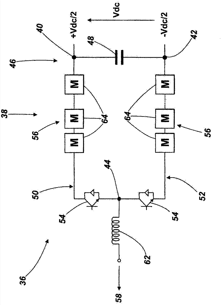
[0046] exist figure 2 A static synchronous compensator 36 according to an embodiment of the invention is shown in .

[0047] The static synchronous compensator 36 includes a primary compensation branch 38 having a first DC terminal 40 , a second DC terminal 42 and an AC terminal 44 , and a secondary compensation branch 46 including a DC link capacitor 48 . The primary compensation branch 38 defines a first branch portion 50 and a second branch portion 52, each branch portion 50, 52 including a switching element 54 at a respective one of the first DC terminal 40 and the second DC terminal 42 Between the AC terminal 44 the switching element 54 is connected in series with a chain-link converter 56 .

[0048] exist figure 2 In the illustrated embodiment, the respective switching elements 54 of the first and second branch sections 50, 52 are connected to the AC terminal 44, and the respective link converters 56 of the first and second branch sections 50, 52 are connected to Re...


PUM


Abstract

A static synchronous compensator (36) for use in reactive power compensation, the static synchronous compensator (36) comprising at least one primary compensator limb (38) including first and second DC terminals (40, 42), and an AC terminal (44) for connection in use to an AC network (58), the or each primary compensator limb (38) defining first and second limb portions (50, 52), each limb portion (50, 52) including at least one switching element (54) connected in series with a chain-link converter (56) between a respective one of the first and second DC terminals (40, 42) and the AC terminal (44), the switching elements (54) of the first and second limb portions (50, 52) being operable to switch the respective chain-link converters (56) in and out of circuit between the respective DC terminal (40, 42) and the AC terminal (44) and the chain-link converters (56) being operable to generate a voltage waveform at the AC terminal (44); and a secondary compensator limb (46) including at least one DC link capacitor (48) connected between the first and second DC terminals (40, 42), the secondary compensator limb (46) being connected in parallel with the or each primary compensator limb (38).

Description

technical field [0001] The invention relates to a static synchronous compensator used in reactive power compensation. Background technique [0002] In high voltage direct current power transmission, alternating current (AC) power is converted to high voltage direct current (DC) power for transmission over overhead lines and / or submarine cables. This conversion reduces the cost per kilometer of wire and / or cable, making it cost-effective when power needs to be transmitted over long distances. Once the transmitted power reaches its destination, the high voltage DC power is converted back to AC power before being distributed to the local network. [0003] Under different network conditions, power transmission over AC transmission lines may experience fluctuations in voltage characteristics, which may cause deviations from standard values. Such fluctuations can be minimized by reactive power exchange between the regulating device and the AC transmission line. Such regulating ...

Claims


Application Information

Patent Timeline
Patent Type & Authority Applications(China)
IPC IPC(8): H02J3/18H02M7/483
CPCH02J3/1835H02M7/49H02J3/1857Y02E40/16Y02E40/26H02M2007/4835Y02E40/30Y02E40/12H02M7/217Y02E40/10Y02E40/20H02M7/4835H02M1/0095
Inventor 威廉·克鲁克斯戴维·特雷纳科林·奥茨
Owner ALSTOM TECH LTD
Why Eureka
Try Eureka