Low layer count reflective polarizer with optimized gain

a reflective polarizer and low layer count technology, applied in the field of multi-layer optical films, can solve the problems of reducing the transmission of light of the desired polarization in the optical system, reducing the color over the visible spectrum control difficulty of microlayer stacks that have neither very small nor very large reflectivities, and exemplary gain and color performance, and substantially avoiding off-axis gain peaks

Active Publication Date: 2011-05-05
3M INNOVATIVE PROPERTIES CO
View PDF97 Cites 82 Cited by
  • Summary
  • Abstract
  • Description
  • Claims
  • Application Information

AI Technical Summary

Benefits of technology

[0023]We therefore describe here, among other things, multilayer reflective polarizers that utilize new combinations of design features to provide exemplary gain and color performance while substantially avoiding the off-axis gain peaks. We describe, for example, new selection criteria for the polymer materials used in the reflective polarizer that increase the in-plane index differences Δnx, Δny (while providing a suitable out-of-plane index difference Δnz) to an extent that the pass axis reflectivity component associated with the microlayers, while still much smaller than the block axis reflectivity, is large enough to overcome the angular dependence of the Fresnel surface reflectivity of the outer surfaces so as to avoid the off-axis gain peaks. The selection criteria are also fortuitously compatible with low layer count films.

Problems solved by technology

Furthermore, exact matching of the two y indices and the two z indices may not be possible in some multilayer systems, and if the z-axis indices are not matched, introduction of a slight mismatch may be desired for in-plane indices n1y and n2y.
Unless the polarizer is laminated on both sides to an existing glass component or to another existing film with clear optical adhesive, such surface reflections will reduce the transmission of light of the desired polarization in the optical system.
Microlayer stacks that have neither very small nor very large reflectivities are more difficult to control for color over the visible spectrum.

Method used


Image

  • Low layer count reflective polarizer with optimized gain
  • Low layer count reflective polarizer with optimized gain
  • Low layer count reflective polarizer with optimized gain

Examples


Embodiment Construction

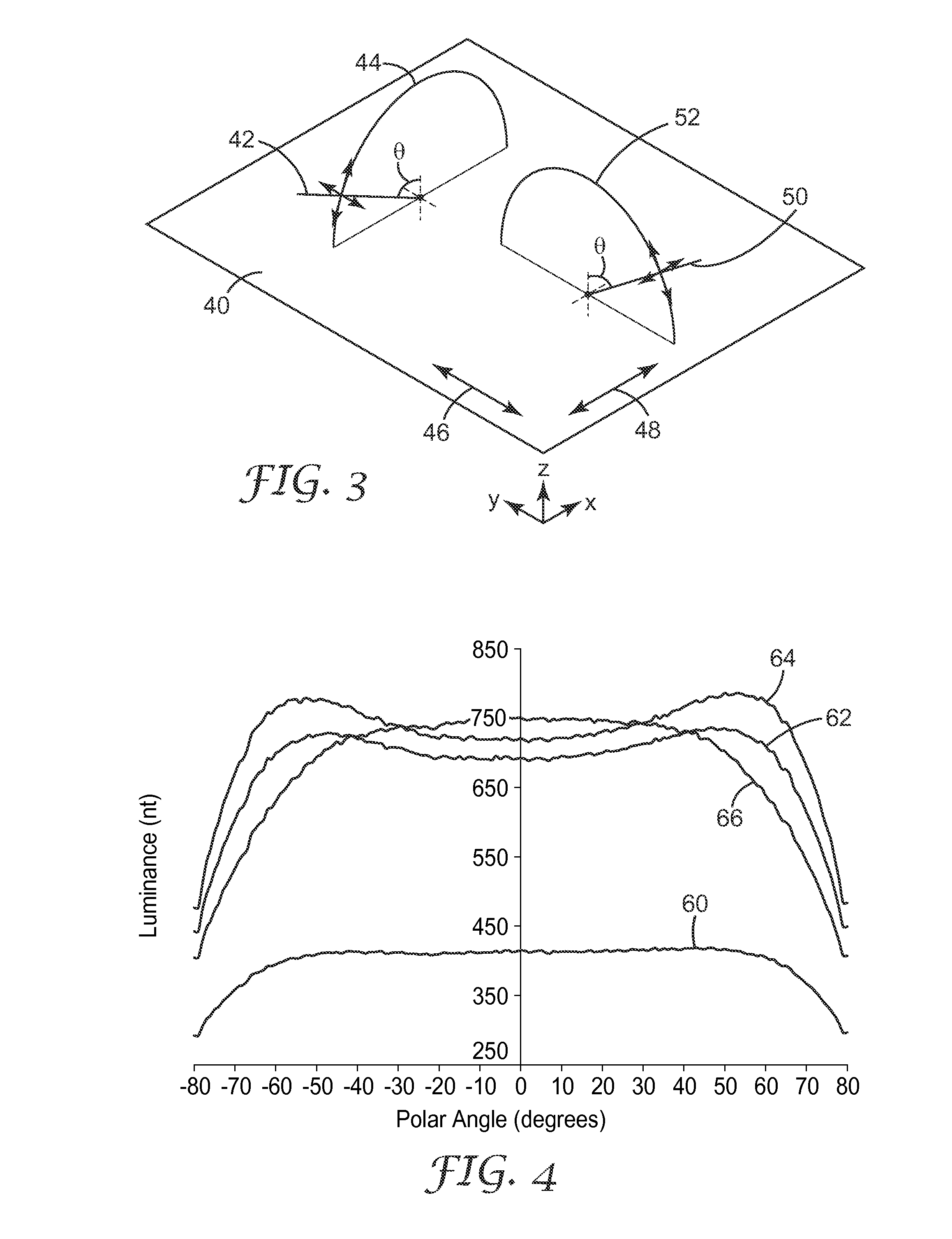
[0040]In order to more clearly describe the off-axis gain behavior observed in commercially available reflective polarizers, we provide in FIG. 3 a perspective view of an optical film 40 in relation to a global x-y-z Cartesian coordinate system. The film 40 may be a multilayer reflective polarizer, in which case the x-, y-, and z-axes can be identical to the local x-, y-, and z-axes discussed above. Alternatively, the film 40 may be another optical film or surface, e.g., the front surface of a display system. As shown, film 40 is laid flat, parallel to the x-y plane.

[0041]In reference to traditional polarizing films, light can be considered to be polarized in two orthogonal planes, where the electric vector of the light, which is transverse to the propagation direction of the light, lies within a particular plane of polarization. In turn, the polarization state of a given light ray can be resolved into two orthogonal polarization states: p-polarized and s-polarized light. P-polarize...


PUM


Abstract

Multilayer reflecting polarizing films are disclosed having increased in-plane refractive index differences between adjacent microlayers along both the pass and block axis, and having negative refractive index differences between adjacent microlayers along the thickness or z-axis. Major front and back surfaces of the film exposed to air provide a Fresnel reflectivity component to the pass axis reflectivity, and the microlayers provide a microlayer component to the pass axis reflectivity, such microlayer component preferably having a reflectivity of p-polarized light that increases with incidence angle faster than the Fresnel reflectivity component decreases so as to substantially avoid off-axis gain peaks for p-polarized light. The films preferably utilize a relatively small total number of microlayers, arranged in a single coherent stack with monotonic optical repeat unit thickness profile, and at least some microlayers preferably include polyethylene naphthalate or a copolymer thereof.

Description

RELATED APPLICATIONS[0001]This application claims benefit of U.S. Provisional Patent Application No. 61 / 040,910, filed on Mar. 31, 2008, the disclosure of which is incorporated by reference in its entirety.FIELD OF THE INVENTION[0002]This invention relates generally to multilayer optical films, with particular application to such films configured as polarizers that are suitable for use in backlights for visual display systems.BACKGROUND[0003]Multilayer optical films, i.e., films that provide desirable transmission and / or reflection properties at least partially by an arrangement of microlayers of differing refractive index, are known. It has been known to make such multilayer optical films by depositing a sequence of inorganic materials in optically thin layers (“microlayers”) on a substrate in a vacuum chamber. Inorganic multilayer optical films are described, for example, in textbooks by H. A. Macleod, Thin-Film Optical Filters, 2nd Ed., Macmillan Publishing Co. (1986) and by A. T...

Claims


Application Information

Patent Timeline
Patent Type & Authority Applications(United States)
IPC IPC(8): G02B5/30
CPCG02B5/3066G02B5/305G02B5/3041G02B5/3083G02B27/283
Inventor DERKS, KRISTOPHER J.WEBER, MICHAEL F.HART, SHANDON D.STOVER, CARL A.
Owner 3M INNOVATIVE PROPERTIES CO
Why Eureka
Try Eureka