Side-emitting step index fiber

a fiber and step index technology, applied in the direction of fiber light guides, instruments, manufacturing tools, etc., can solve the problems of difficult to produce appropriate preforms, complex use of core geometries disclosed in jp 9258028 a2, and inefficient light coupling, etc., to achieve easy scalable, economic production, and not flammable

Active Publication Date: 2011-05-05
SCHOTT AG
View PDF5 Cites 82 Cited by
  • Summary
  • Abstract
  • Description
  • Claims
  • Application Information

AI Technical Summary

Benefits of technology

[0018]Against this background, it is an object of the invention to provide a side-emitting step index fiber that can be produced economically and couples the light out laterally in an efficient fashion, the aim being for the effect to be e

Problems solved by technology

The production of side-emitting fibers via such core geometries is, however, attended by the problem that coupling out the light is very inefficient in this case.
Furthermore, making use of the core geometries disclosed in JP 9258028 A2 for fibers made from glass is very complex because it is very difficult to produce appropriate preforms such as are required for fiber drawing.
There are difficulties here in producing relatively long fibers with uniformly side-emitting properties, since the guiding of light in the core is reduced by absorption by the added particles in the core, since there are no particles that scatter completely, but only ones that scatter nearly all the incident light.
The coupling-out effect can therefore be scaled only with great difficulty, and this renders reproducible results in fiber drawing a matter of extreme complexity extending as far as near impossibility at least for fibers over 3 m in length, at least when the aim is to produce glass fibers.
Thus, it is known from the prior art that crystallization reactions between core glasses and cladding glasses are undesirable, since the crystallites in the interface between core and cladding can serve as scattering centers such that light is coupled out of the fiber and therefore reduces its optical conductivity.
This effect is generally undesirable in the case of optical waveguides and, as described in German patent DE 102 45 987 B3, glass fibers are normally developed in a targeted way such that no crystallization takes place between core and cladding.
However, it has emerged in experiments that the crystallization process can be set and controlled during fiber drawing only with difficulty, a

Method used


Image

  • Side-emitting step index fiber
  • Side-emitting step index fiber
  • Side-emitting step index fiber

Examples


Embodiment Construction

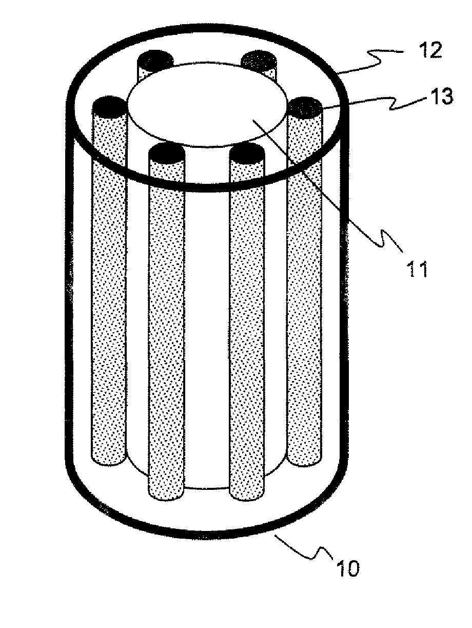
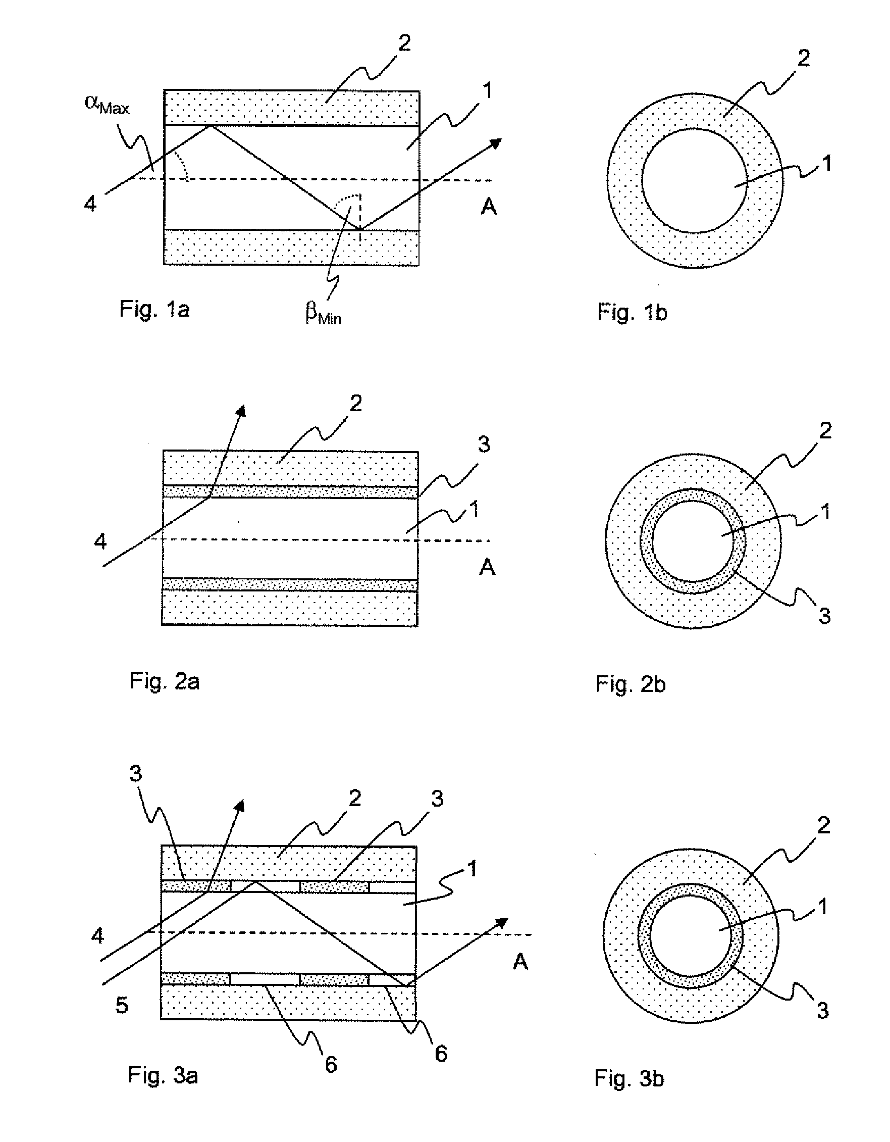
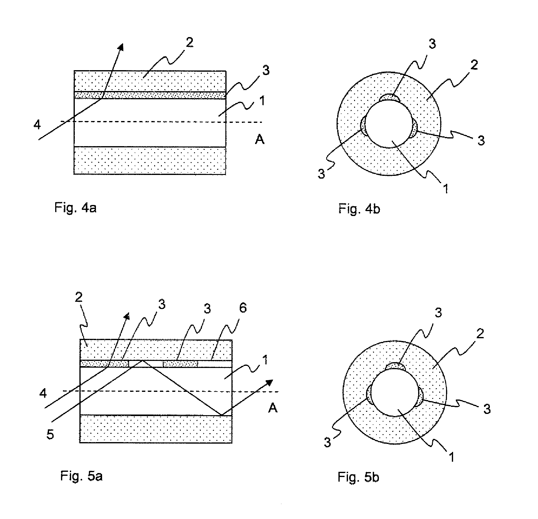
[0144]All the drawings are schematic, the diameters of their elements are not to scale, and also the relative ratios of dimensions of all the elements to one another can deviate from the drawings in the real objects.

[0145]FIG. 1a shows the longitudinal section along the fiber axis (A) of a step index fiber from the prior art. This step index fiber consists of a core (1) having the refractive index n1. The entire periphery of said core is surrounded by the cladding (2), which has the refractive index n2. Incident light (4) is guided in the core (1) because total reflection occurs at the cladding (2) by virtue of the smaller refractive index n2. However, the condition of total reflection is possible only up to a limiting angle of the light striking the cladding, which angle depends on the values of the refractive indices of core and cladding. The limiting angle βMin can be calculated by sin(βMin)=n2 / n1, βMin being measured from a plane perpendicular to the fiber axis.

[0146]The refract...


PUM

PropertyMeasurementUnit
Diameteraaaaaaaaaa
Angleaaaaaaaaaa
Angleaaaaaaaaaa

Abstract

Side-emitting step index fibers. Between core and cladding, the side-emitting step index fibers have scattering centers that ensure the coupling out of light from the fiber. The side-emitting step index fibers are produced by preforms that contain inlay rods, in which the scattering centers are embedded and which are applied to the outer region of the fiber core during fiber drawing. Alternatively, at least one inlay tube can be used.

Description

CROSS REFERENCE TO RELATED APPLICATIONS[0001]This application is a U.S. National Stage Entry under 35 U.S.C. §371 of International Application No. PCT / EP2009 / 000702, filed on Feb. 3, 2009, which claims the benefit of German Patent Application No. 10 2008 034 791.4, filed Jul. 25, 2008, German Patent Application No. 10 2008 009 139.1, filed Feb. 14, 2008, and German Patent Application No. 10 2008 009 137.5, filed Feb. 14, 2008, the entire contents of each of which are incorporated herein by reference.BACKGROUND OF THE INVENTION[0002]1. Field of the Invention[0003]The invention relates to side-emitting step index fibers, methods for producing such, and their applications.[0004]2. Description of Related Art[0005]Step index fibers are understood as light-guiding fibers, the light being guided in the fiber core by total reflection of the light guided in the core at the cladding enclosing the fiber core along the fiber axis. The total reflection occurs whenever the cladding has a lower re...

Claims


Application Information

Patent Timeline
IPC IPC(8): G02B6/028
CPCC03B37/01211C03B37/028C03B2203/10C03B2203/18G02B6/04C03C13/046G02B6/001G02B6/02052C03B2205/32Y02P40/57
Inventor ALKEMPER, JOCHENHOPPE, BERNDBERND, SCHULTHIESRITTER, SIMONE MONIKAHENZE, INKAWOLFF, DETLEFCURDT, AXEL
Owner SCHOTT AG
Why Eureka
Try Eureka