Passive optical network system and optical line terminal

a technology of optical network system and optical line terminal, which is applied in the direction of multiplex communication, instruments, star/tree networks, etc., can solve the problems of increasing power consumption, increasing the speed of pon, and all communication services for user sides become scarce, so as to reduce power consumption. the effect of a large degr

Inactive Publication Date: 2011-05-05
HITACHI LTD
View PDF7 Cites 33 Cited by
  • Summary
  • Abstract
  • Description
  • Claims
  • Application Information

AI Technical Summary

Benefits of technology

[0014]An object of the present invention is to provide a passive optical network system and an optical line terminal that can reduce power consumption more gr

Problems solved by technology

However, conversely, when a trouble occurs in the PON system, all the communication services for user sides become scarce.
Furthermore, increase of the speed of PON follows increase of power consumption.
Accordingly, with respect to the circuit constructing the protection (backup) line, it is natural that increase of the speed thereof likewise increases power consumption.
Therefore, PON having a protection (backup) line consumes power which is nearly twice as much as PON having no protection (backu

Method used


Image

  • Passive optical network system and optical line terminal
  • Passive optical network system and optical line terminal
  • Passive optical network system and optical line terminal

Examples


Embodiment Construction

[0077]An embodiment according to the present invention will be described with reference to the accompanying drawings. The substantially same sites are represented by the same reference numerals, and thus the duplicative description thereof is omitted.

1. System Construction

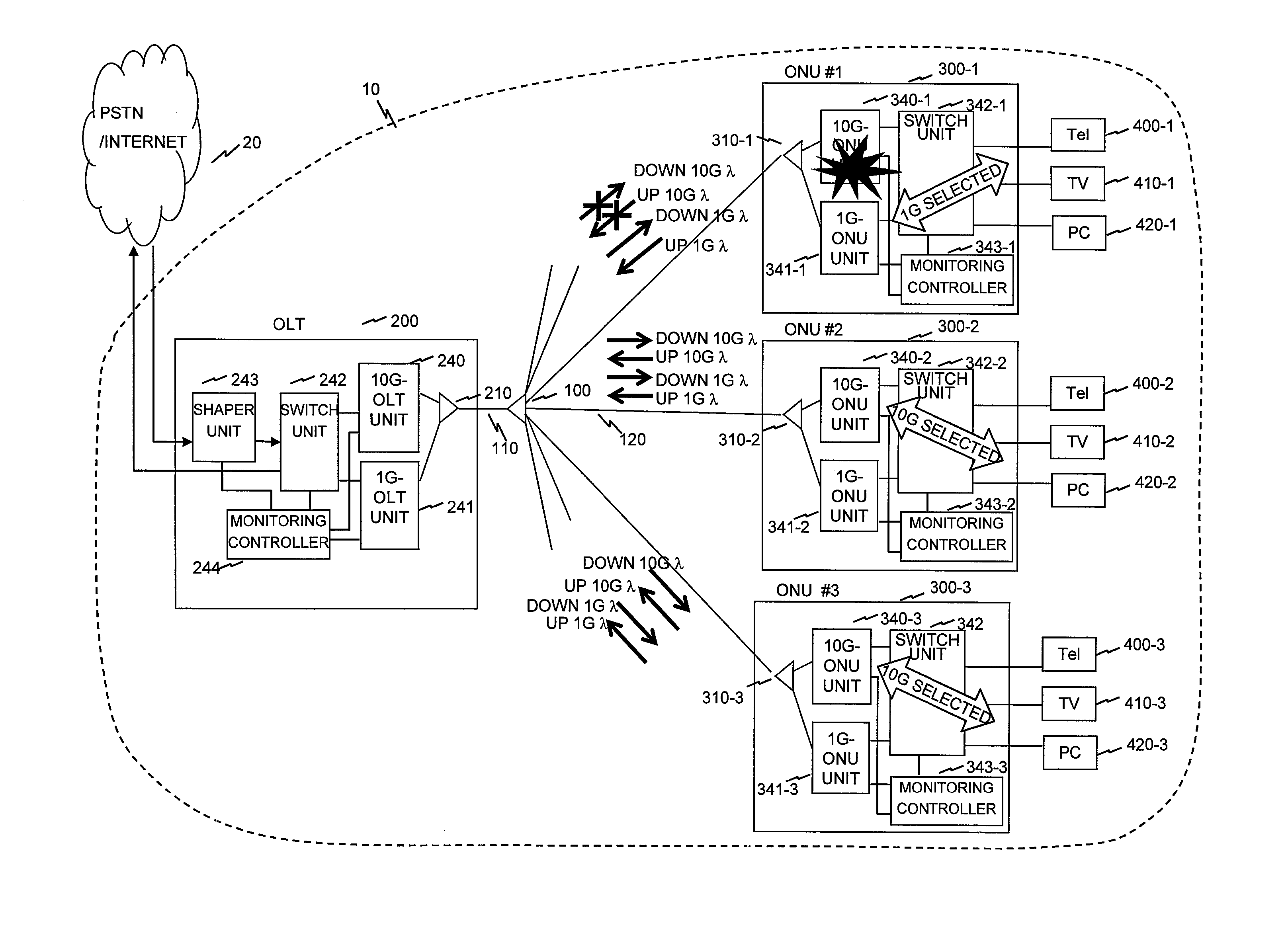
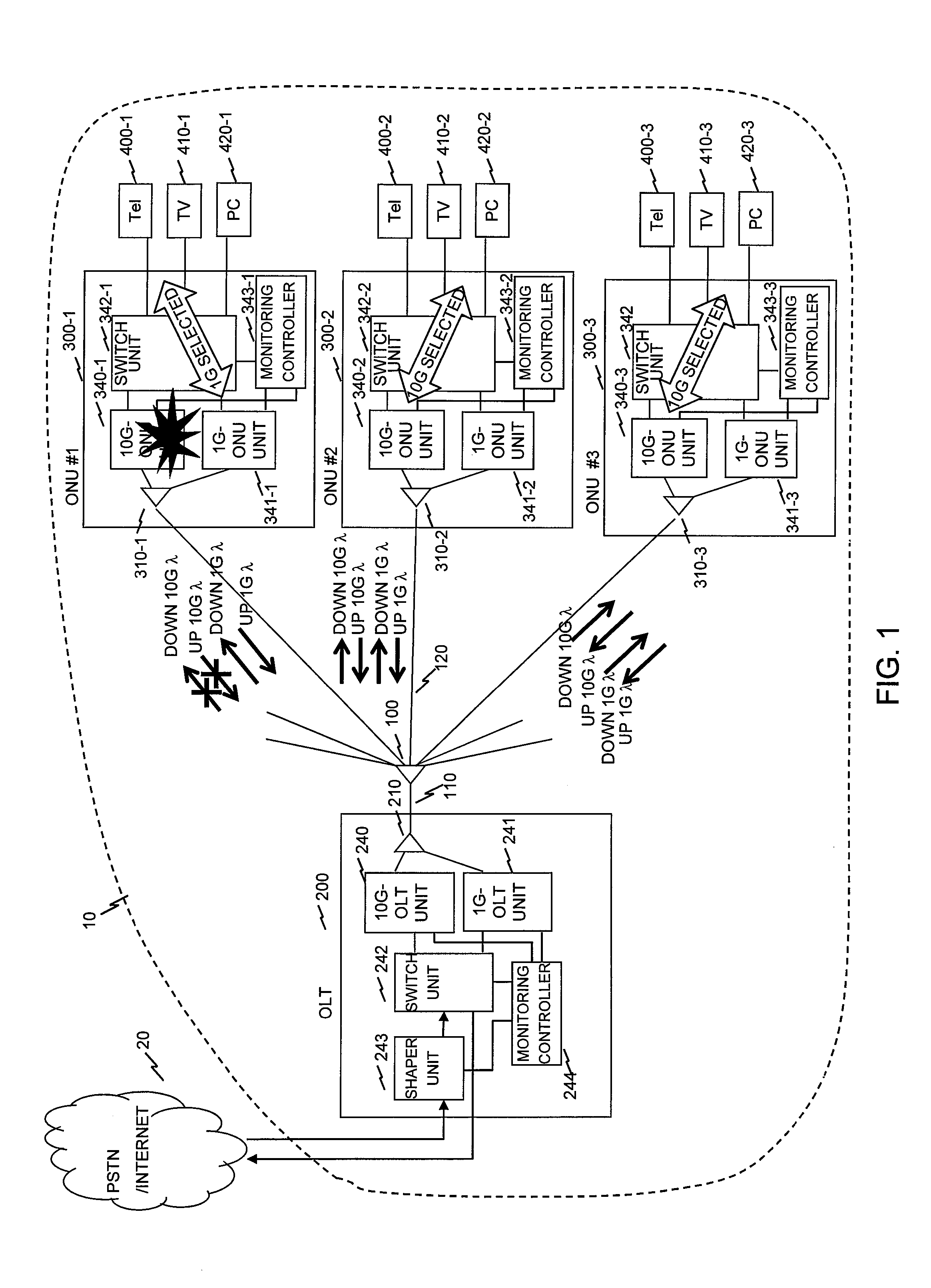
[0078]A PON system according to an embodiment of the present invention will be described with reference to FIG. 1.

[0079]Here, FIG. 1 is a functional block diagram of the PON system.

[0080]In FIG. 1, PON 10 is connected to a PSTN / Internet 20 to transmit / receive data. PON 10 has an optical splitter 100, a main (trunk) fiber 110, branch lines 120, OLT 200, ONUs 300, telephones 400, TVs 410 and personal computers (PC) 420. OLT 200 has a 10G-OLT unit 240, a 1G-OLT unit 241, a switch unit 242, a shaper unit 243, and a monitoring controller 244. OLT 200 is connected to the main fiber 110 through a WDM filter 210. OLT 200 is connectable to plural (for example, 32) ONUs 300 through one main fiber 110, the optical splitter 10...


PUM


Abstract

A transmission speed of a protection (backup) line using 1G-OLT unit and 1G-ONU unit is set to be lower than a transmission speed of a working (primary) line using 10G-OLT unit and 10G-ONU unit. A priority and band of each communication service in ONU are preset individually and separately every LLID for a working (primary) line and a protection (backup) line. When bands are allocated to the protection (backup) line, the band allocation is performed so as to secure a minimum number of bands of each communication service. A monitoring controller refers to a predetermined band information table according to an operation state of the working (primary) line or the protection (backup) line with respect to a downstream signal packet.

Description

CLAIM OF PRIORITY[0001]The present application claims priority from Japanese patent application JP 2009-247845 filed on Oct. 28, 2009, the content of which is hereby incorporated by reference into this application.BACKGROUND OF THE INVENTION[0002]1. Field of the Invention[0003]The present invention relates to a passive optical network system and an optical line terminal, and particularly to a passive optical network system and an optical line terminal in which plural optical network units share an optical transmission line.[0004]2. Description of the Related Art[0005]Passive Optical Network (PON) has Optical Line Terminal (OLT) and plural Optical Network Units (ONU). PON converts a signal from a terminal (PC or the like) connected to ONU to an optical signal, passes the optical signal through ONU, a branch (feeder) optical fiber and then an optical splitter while the optical signal is multiplexed optically (time-divisionally) with a main optical fiber to OLT, and then transmits the ...

Claims


Application Information

Patent Timeline
IPC IPC(8): H04J14/00H04L12/44
CPCH04B10/032H04Q2011/0081H04Q11/0067H04B10/272
Inventor KIMURA, MITSUNOBU
Owner HITACHI LTD
Why Eureka
Try Eureka