Method of manufacturing ceiling fan blades

Inactive Publication Date: 2011-05-05
LIAO HSIEN CHIN
View PDF3 Cites 4 Cited by
  • Summary
  • Abstract
  • Description
  • Claims
  • Application Information

AI Technical Summary

Benefits of technology

[0013]The primary object of the present invention is to provide a method of manufacturing a ceiling fan blade which is simplified in the working proc

Problems solved by technology

The cost must be increased due to the fussy working procedures.
However, since there is lead in the solvent, the environment will be polluted and the solvent itself will cause the damage to the human being.
Even though the patterned paper layer 11 is sprayed with an adhesive paint layer 12 and the shining-paint layer 13, it still can be disrupted due to scraping, leading to an unbeautiful appearance.
After the blade 10 is attached to the patterned paper layer 11, unfortunately the primary color

Method used


Image

  • Method of manufacturing ceiling fan blades
  • Method of manufacturing ceiling fan blades
  • Method of manufacturing ceiling fan blades

Examples


Embodiment Construction

[0022]The following descriptions are of exemplary embodiments only, and are not intended to limit the scope, applicability or configuration of the invention in any way. Rather, the following description provides a convenient illustration for implementing exemplary embodiments of the invention. Various changes to the described embodiments may be made in the function and arrangement of the elements described without departing from the scope of the invention as set forth in the appended claims.

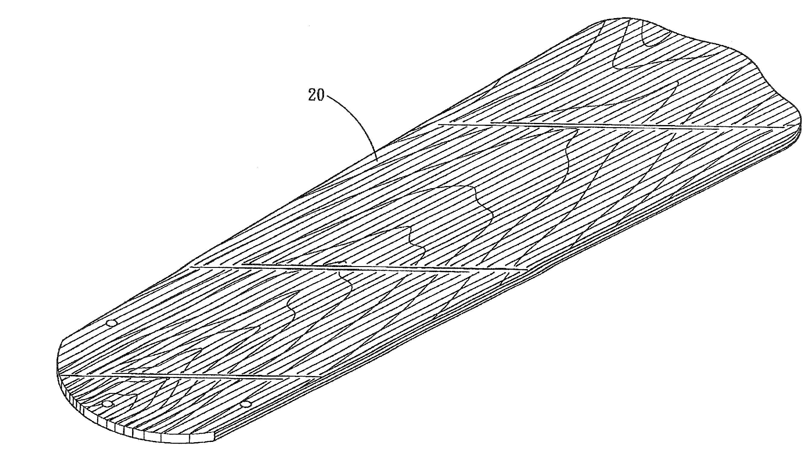
[0023]Referring to FIGS. 4-5, a ceiling fan blade 20 which is installed on the ceiling fan C (as shown hi FIG. 3) in accordance with a preferred embodiment of the present invention is made of wood. The manufacturing process of the ceiling fan blade 20 comprises the following step:

[0024]1. printing a patterned layer 21 on the surface of the ceiling fan blade 20;

[0025]2. applying infrared ray to heat the patterned layer 21 at 100-150 degrees centigrade for 1-3 minutes; and

[0026]3. spraying a shinin...


PUM

PropertyMeasurementUnit
Angleaaaaaaaaaa

Abstract

A method of manufacturing a ceiling fan blade which includes the steps of printing a patterned layer on a surface of the ceiling fan blade, applying infrared ray to heat the patterned layer at 100-150 degrees centigrade for 1-3 minutes, and spraying a shining layer on a surface of the patterned layer, the shining layer being made of a powder coating material mixed with a thermosetting powder coating material, the power coating material being selected from a group consisting of tertiary amine or imidazole and its derivatives, the thermosetting powder coating material being selected from a group consisting of hydroxyl group polyester resin, carboxylic group polyester resin, acid anhydride, phenol resin, aromatic amine or aliphatic amine, whereby the method is simplified in working procedures can be and environmentally friendly.

Description

CROSS-REFERENCE[0001]This is a continuation-in-part of the co-pending patent application Ser. No. 11 / 934,061.BACKGROUND OF THE INVENTION[0002]1. Field of the Invention[0003]The present invention relates to a method of manufacturing ceiling fan blades, and more particularly to one which is low in cost and environmentally friendly.[0004]2. Description of the Prior Art[0005]Referring to FIGS. 1-2, one side A of a conventional fan blade 10 comprises a patterned paper layer 11, three adhesive paint layers 12 and a shining paint layer 13. The patterned paper layer 11 is attached to a surface A of the fan blade 10. The three 10 adhesive paint layers 12 are formed on a surface of the patterned paper layer 11 by spraying. The shining paint layer 13 is formed on the surface of the three adhesive paint layers 12 by spraying.[0006]Since the blade 10 is made of wood, the surface A of the blade 10 must be rubbed flat at the time of attaching the patterned paper layer 11. Additionally, since 15 th...

Claims


Application Information

Patent Timeline
IPC IPC(8): B05D3/06
CPCF04D25/088F04D29/388F04D29/023F05D2230/90F05D2300/44
Inventor LIAO, HSIEN-CHINLIN, KU-HUA
Owner LIAO HSIEN CHIN
Why Eureka
Try Eureka