Laminoplasty Rod System

a rod system and laminoplasty technology, applied in the field of laminoplasty rod system, can solve the problems of inability to fully recover, lose mobility and/or permanent physical damage, and may also undergo other compression problems in the spine, so as to achieve less in-situ contouring

Active Publication Date: 2011-05-05
LIFE SPINE INC
View PDF40 Cites 16 Cited by
  • Summary
  • Abstract
  • Description
  • Claims
  • Application Information

AI Technical Summary

Benefits of technology

[0014]The present invention is an improved laminoplasty implant/implant system that provides a better fit with existing anatomies, less in-situ contouring and fewer implant iterations than existing laminoplasty implant/implant systems. Particularl

Problems solved by technology

It can thus be appreciated that any compromise to or trouble with the spine can cause various medical problems.
The spine may also undergo other compression problems.
If left untreated,

Method used


Image

  • Laminoplasty Rod System
  • Laminoplasty Rod System
  • Laminoplasty Rod System

Examples


Embodiment Construction

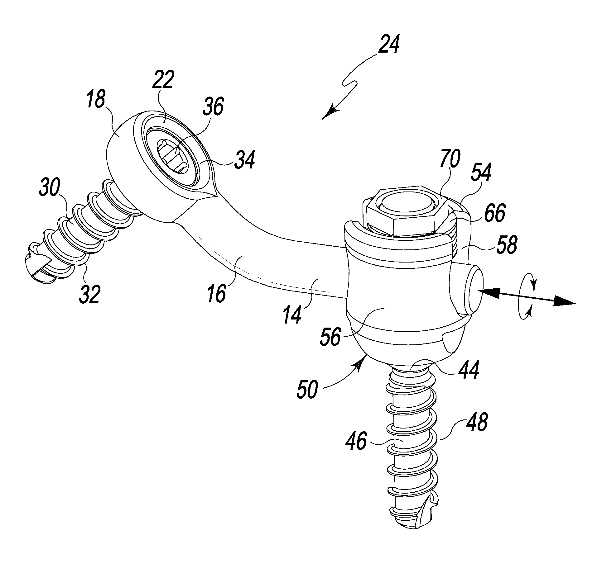
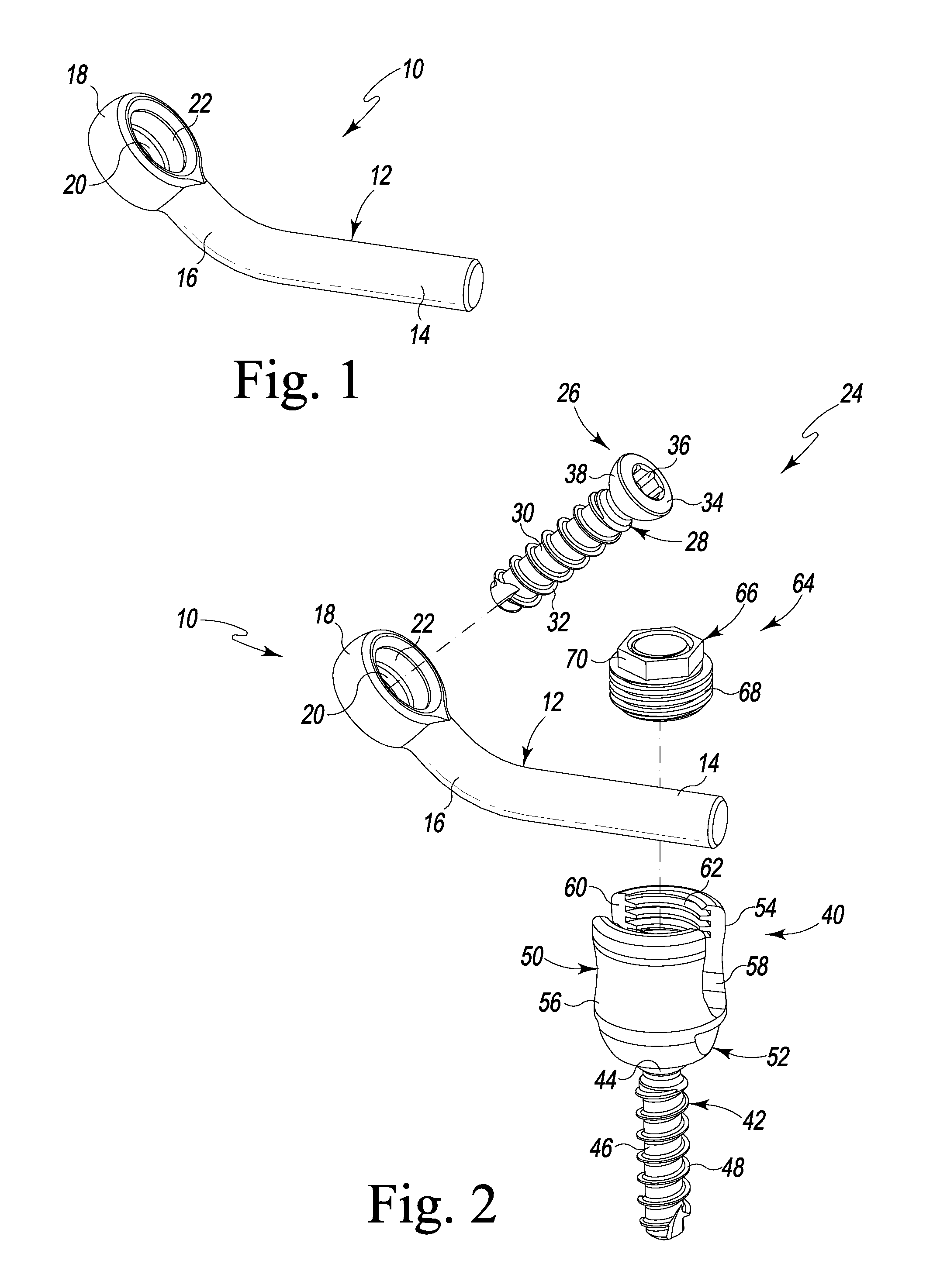
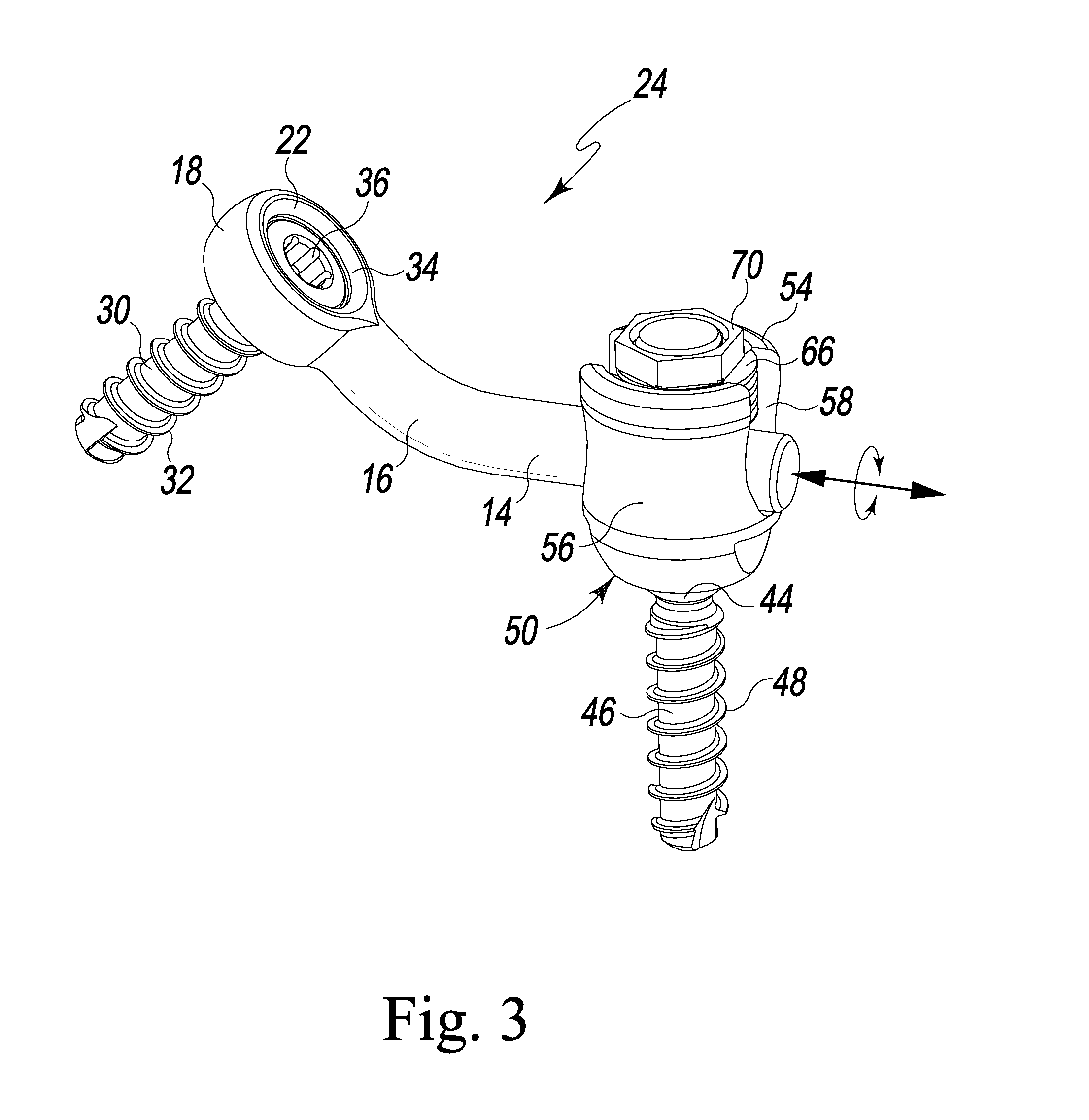
[0029]Referring to FIG. 1 there is depicted an exemplary embodiment of a spinal implant fabricated as a laminoplasty rod, generally designated 10, fashioned in accordance with the principles of the present invention. The laminoplasty rod 10 is formed of a biocompatible material such as titanium, stainless steel, or the like. If desired, biocompatible plastics (e.g. PEEK), composites, polymers or the like may be used. The laminoplasty rod 10 is defined by a body 12 having a first rod portion 14, a second rod portion 16 and a bone screw attachment configuration or portion 18, it being understood that the nomenclature first and second is arbitrary.

[0030]The first rod portion 14 is formed to be received in and attached to a polyaxial spinal rod bone screw assembly such as that depicted in FIGS. 2-4 (i.e. polyaxial spine rod bone screw assembly or spine rod holder assembly 40). Particularly, the first rod portion 14 is configured to be received in slots 58, 60 of a polyaxial head 50 of t...


PUM


Abstract

A laminoplasty rod and rod system that allows for variable angulation, translation (distraction and/or compression) and rotation of a spinal lamina bone portion associated with a laminoplasty, prior to fixation thereof. The laminoplasty rod is configured for use with a polyaxial spinal rod bone screw assembly that is adapted to be anchored to the vertebra associated with the laminoplasty, and is attachable to the spinal lamina bone portion. The laminoplasty rod system provides positional attachment of the laminoplasty rod to the spinal components associated with the laminoplasty and fixation thereof in various orientations. The laminoplasty rod system is characterized by a configured laminoplasty rod that fits into or onto the head of a polyaxial spinal rod bone screw assembly. A bone screw boss, defining a bone screw attachment configuration, is formed at one end of the laminoplasty rod. Preferably, but not necessarily, the bone screw boss is situated at an angled end of the rod having a pre-defined bend that provides for greater variation in rod orientation.

Description

RELATED APPLICATIONS[0001]This patent application claims the benefit of and / or priority under 35 U.S.C. §119(e) to U.S. Provisional Patent Application Ser. No. 61 / 257,312 filed Nov. 2, 2009, entitled “Laminoplasty Rod System” the entire contents of which is specifically incorporated herein by this reference.BACKGROUND OF THE INVENTION[0002]1. Field of the Invention[0003]The present invention relates to procedures and devices for treating problems with the spine and, in particular, to procedures and devices for relieving pressure on the spinal cord.[0004]2. Background Information[0005]The spinal cord and nerve roots in the neck are surrounded and protected by the cervical vertebrae. These bones have an opening called the spinal canal through which the spinal cord passes. Ligaments and blood vessels are also present in the spinal canal. The nerve roots start at the spinal cord and pass through an opening between the vertebrae called the intervertebral foramen (or neural foramen). From...

Claims


Application Information

Patent Timeline
IPC IPC(8): A61B17/70A61B17/86
CPCA61B17/7005A61B17/7007A61B17/7071A61B17/7032A61B17/7067A61B17/7011
Inventor BUCCI, KARA A.PREDICK, DANIELAN, HOWARD S.
Owner LIFE SPINE INC
Why Eureka
Try Eureka