Method for producing a tape product having diagnostic aids

a technology of diagnostic aids and tape products, which is applied in the direction of controlling lamination, paper/cardboard articles, transportation and packaging, etc., can solve the problems of analysis methods described, diagnostics are constantly under cost pressure, and analysis tapes must be produced cost-effectively, so as to improve positioning accuracy, simplify the transfer, and increase the positioning accuracy

Active Publication Date: 2011-05-12
ROCHE DIABETES CARE INC
View PDF17 Cites 6 Cited by
  • Summary
  • Abstract
  • Description
  • Claims
  • Application Information

AI Technical Summary

Benefits of technology

In other embodiments, the method and the device are configured in such a way that always in each case one diagnostic auxiliary label is applied simultaneously on the vacuum roller. This simplifies the transfer and increases the positioning accuracy.
A further improvement in the positioning accuracy concerns the configuration of the guidance and the drive of the carrier tape at the location where the diagnostic auxiliary label is transferred, that is to say at the location of the labeling device. Thus, in particular, the carrier tape can be guided in planar fashion at this location, for example using a support on a side opposite to the labeling side of the carrier tape, which has a counterpressure with respect to the vacuum roller. It is possible, however, to provide an application roller at this location where the diagnostic auxiliary label is transferred to the carrier tape, wherein the carrier tape is guided through a roller gap between the application roller and the vacuum roller. In this case, the carrier tape can be guided in planar fashion by means of the application roller, that is to say without significant deflection by the application roller. It is possible, however, for the application roller to be configured in such a way that the carrier tape at least partly follows the circumference of the application roller, that is to say is deflected by said application roller. In this case, the application roller can be a part of the drive of the carrier tape. This development of the invention has the advantage that the drive of the carrier tape is effected directly at the location where the auxiliary labels are applied, such that, by way of example, stretching effects of the carrier tape are only of slight significance. The spatial uniting of drive and application location of the auxiliary labels thus brings about a considerable improvement in the accuracy of the positioning of the auxiliary labels on the carrier tape.
A further advantage of using a vacuum roller for applying the auxiliary labels to the carrier tape consists in the possibility of effecting corrective intervention in the application. This is advantageous in particular since quality assurance is of considerably higher significance in the production of medical products than in the field of conventional labeling machines in which all labels are applied non critically and without consideration of the quality thereof to an article to be labeled.

Problems solved by technology

At the same time, however, the analysis tapes have to be produced cost-effectively since medical diagnostics is under constantly increasing cost pressure.
It has been found here during use in practice, however, that the analysis method described in EP 1 593 434 A2 is restricted in terms of throughput, such that labeling tolerances which exceed the predetermined maximum tolerances may occur at tape speeds of the carrier tape of tens of m / min.
A further disadvantage of the known labeling methods, such as the method known from EP 1 593 434 A2, for example, is that large amount of rejects arise during labeling.
Thus, by way of example, the stamping and removal of the stamping grid as described in EP 1 593 434 A2 are associated with considerable rejects, which, in view of the high quality of the test chemical used and the complex construction of the multitrack label tape used, considerably increases the production costs.

Method used


Image

  • Method for producing a tape product having diagnostic aids
  • Method for producing a tape product having diagnostic aids
  • Method for producing a tape product having diagnostic aids

Examples


Embodiment Construction

The following descriptions of the embodiments are merely exemplary in nature and are in no way intended to limit the present invention or its application or uses.

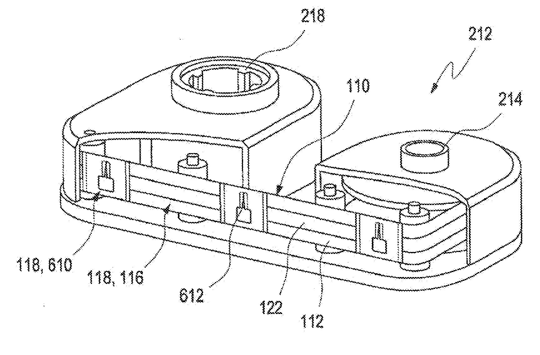
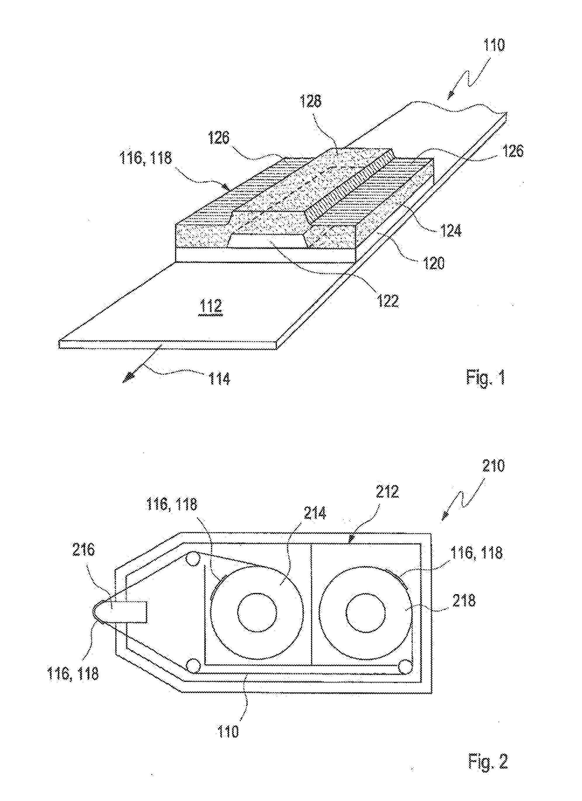
FIG. 1 illustrates one possible exemplary embodiment of an analysis tape 110 such as is known from EP 1 593 434 A2, for example, and such as can be produced for example by a method according to the invention described below. The analysis tape 110 comprises a carrier tape 112, which can be configured for example as a carrier film in the form of a plastic film. Said carrier film can be made very thin, for example, with a thickness of between 10 and 15 μm, for example, and can comprise at least one plastic material, for example polyethylene.

A multiplicity of test fields 116 are applied on the carrier tape 112 in a manner spaced apart in a transportation direction 114. Of these test fields 116, which, by way of example, can be arranged at a distance of 110 mm and can have a length in the transport direction 114 of approximately...


PUM

PropertyMeasurementUnit
speedaaaaaaaaaa
radiusaaaaaaaaaa
radiusaaaaaaaaaa

Abstract

A method for producing an analysis tape for fluid samples, in particular body fluids, is proposed. The method comprises providing a laminate tape having a laminate carrier tape and at least one diagnostic functional layer, and cutting the laminate tape in such a way that a diagnostic auxiliary label arises; transferring the diagnostic auxiliary label to a vacuum roller; and transferring the diagnostic auxiliary label to a carrier tape. In general, at least one vacuum roller is used for the transfer of the diagnostic auxiliary label to the carrier tape. The cutting of the diagnostic functional layer is effected in such a way that a free end of the diagnostic functional layer is lifted off from the laminate carrier tape by guiding the laminate carrier tape around a cutting edge with a small radius, wherein the diagnostic functional layer is cut at a predetermined distance from the lifted off free end by means of a cutting device.

Description

TECHNICAL FIELD OF THE INVENTIONThe invention relates to a method for producing an analysis tape for fluid samples, in particular body fluids. The invention furthermore relates to a device for producing an analysis tape for fluid samples, in particular using a method according to the invention. Methods and devices of this type are generally used for example to produce a tape product comprising diagnostic aids, for example diagnostic aids for a single use. Diagnostic aids of this type can comprise in particular one or more test fields with a detection chemical and / or lancets for obtaining a fluid sample of a body fluid, such as are used in the context of diabetes diagnostics, for example. Other fields of application are also conceivable, however.BACKGROUNDThe examination of blood samples or other samples of body fluids, such as interstitial fluid, for example, enables, in clinical diagnostics, early and reliable identification of pathological states and targeted and astute monitoring...

Claims


Application Information

Patent Timeline
Patent Type & Authority Applications(United States)
IPC IPC(8): B65C9/18B65C9/26
CPCB31D1/021Y10T156/10B32B37/0053B32B2310/0843B32B2310/025B32B2041/04B32B41/00B32B2535/00B32B38/1858B32B38/18B32B38/0008B32B38/0004B32B39/00Y10T156/12B65C9/188
Inventor DAGENBACH, RALFAIGL, DANIELDITSCHER, WOLFGANGSTUBENBORD, PETERHOFSTADT, RONALDKRONTAL, ANDREASLINK, STEFANLURG, KLAUSPFLAESTERER, STEFANTRAPP, ANDREASVOELSCHOW, ERICVETTER, PETERSPRUNG, ULF
Owner ROCHE DIABETES CARE INC
Why Eureka
Try Eureka