Femoral reaming system and method of performing trial reduction

a reaming system and femoral technology, applied in the field of surgical devices, can solve the problems of inexact reamer, series of potential problems, and laborious system, and achieve the effects of increasing accuracy, reducing the number of steps/instruments, and increasing accuracy

Inactive Publication Date: 2011-05-12
SMITH & NEPHEW INC
View PDF4 Cites 42 Cited by
  • Summary
  • Abstract
  • Description
  • Claims
  • Application Information

AI Technical Summary

Benefits of technology

[0026]In another embodiment of the invention, the modular portion is further configured to have a tapered portion. The tapered portion allows for adjustment of the neck axis of the trial neck.
[0035]The invention has several advantages over prior devices and techniques. First, the devices may increase accuracy while decreasing the number of steps / instruments that is required of systems that utilize proximal / distal reaming systems. Increased accuracy may reduce the amount of natural bone removed from the femur and may reduce the amount of further preparation after the initial reaming In addition, reducing the number of steps and instruments may reduce total operation time.
[0036]Second, increased accuracy and decreased number of steps may also be achieved with respect to the method of performing a trial reduction for modular implant designs, at least partially because the trial neck may be oriented in situ without having to remove the reamer construct.

Problems solved by technology

Such systems are labor intensive and time consuming.
Therefore, the reamers may still be inexact in preparing the distal to proximal portions of the femoral canal because of errors such as tolerance stack and human error.
This flexible core can create a series of potential issues.
First issue is the ability to clean the tool core.
Another issue is with the potential of the system binding such that the flexible core creates a “coiling” effect and doesn't allow the reamers to turn and cut due to more torsional resistance of the bone cutting than torsional resistance of the flexible core.
The location of the head / neck assembly relative to the reamer or broach may be difficult to replicate with the implant.
This system also does not facilitate the ability for the proximal and distal reamers to be modular such that a surgeon can have various proximal reamers for a given distal reamer.

Method used


Image

  • Femoral reaming system and method of performing trial reduction
  • Femoral reaming system and method of performing trial reduction
  • Femoral reaming system and method of performing trial reduction

Examples


Embodiment Construction

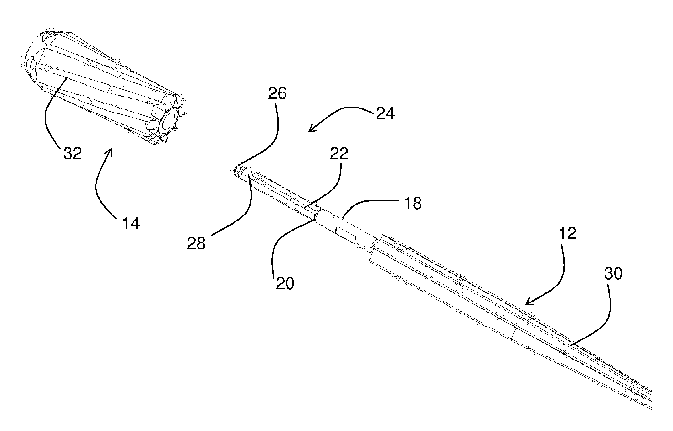
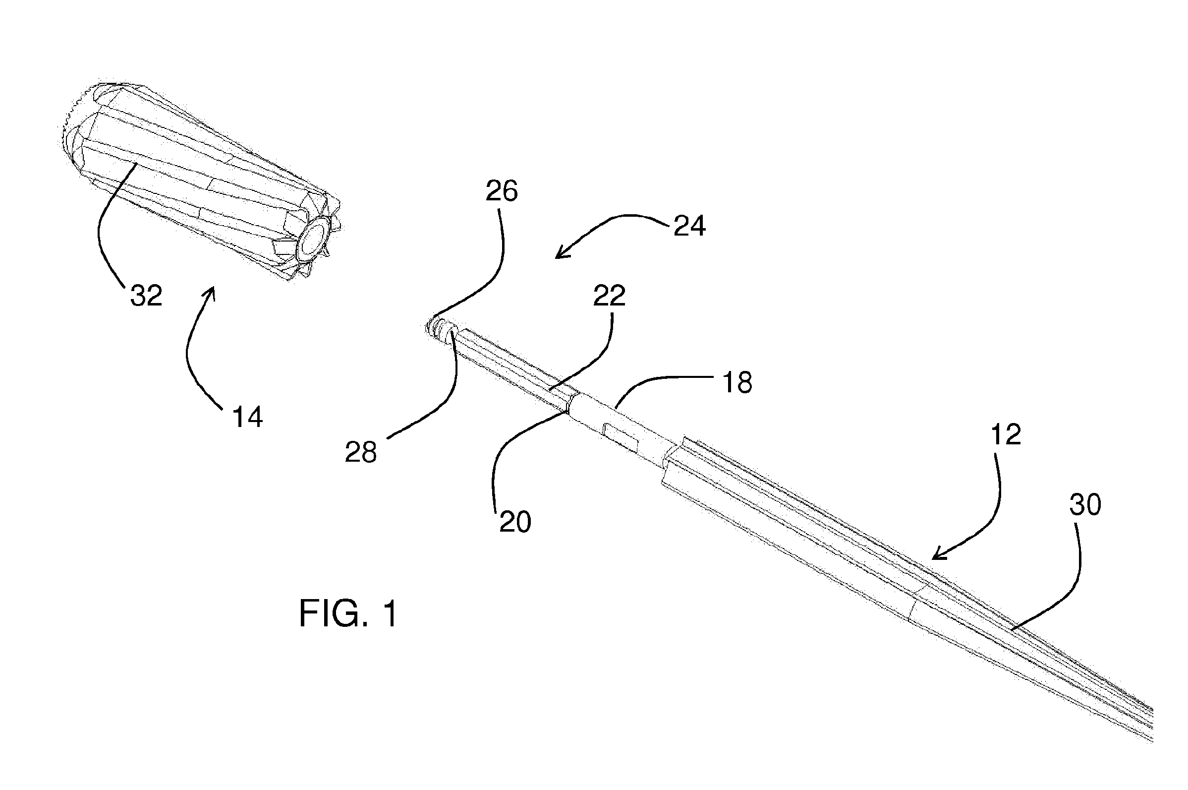
[0050]Referring to the accompanying drawings in which like reference numbers indicate like elements, FIG. 1 is an exploded view of parts of a femoral reamer 10 according to an embodiment of the invention. The femoral reamer 10 includes two major components, a distal reamer 12 and a proximal reamer 14. The distal reamer 12 prepares the femur for receiving a stem of a femoral implant and the proximal reamer 14 prepares the femur for receiving a sleeve of a femoral implant. The distal reamer 12 includes a thick depth shaft 18, a shoulder 20, a distal reamer shaft 22 and a quick connect mating portion 24. The quick connect mating portion 24 includes a mounting tip 26 and a groove 28. The quick connect mating portion 24 is attached to a drill.

[0051]The distal reamer 12 includes right-hand cutting flutes 30 while the proximal reamer 14 includes left-handed cutting flutes 32. The right-handed cutting flutes 30 have edges on the flutes that cut in a forward cutting action when the reamer 10...


PUM


Abstract

An apparatus (10) for removing bone material comprises a distal cutting instrument (12) and a proximal cutting instrument (14). The distal cutting instrument has at least one first cutting edge (30), a shoulder (20), and a shaft portion (22). The shaft portion (22) has an anti-rotation feature. The at least one first cutting edge (30) removes bone material when moved in a first direction. The proximal cutting instrument (14) is removably attached to the shaft portion (22). The proximal cutting instrument (14) has a first end portion (68) and a second end portion (66). The second end portion (66) contacts the shoulder (20) of the distal reamer (12) when the proximal reamer is mounted to the shaft portion (22). The proximal reamer (14) has at least one second cutting edge (32) and an aperture. The aperture is adapted to receive the anti-rotation feature of the shaft portion (22) of the distal reamer (12). The at least one second cutting edge (32) removes bone material when moved in a second direction.

Description

CROSS-REFERENCE TO RELATED APPLICATIONS[0001]This application claims the benefit of U.S. Provisional Applications No. 60 / 826,675, filed Sep. 22, 2006 and No. 60 / 781,025 filed Mar. 10, 2006. The disclosure of each application is incorporated by reference in its entirety.STATEMENT REGARDING FEDERALLY SPONSORED RESEARCH OR DEVELOPMENT[0002]Not Applicable.APPENDIX[0003]Not Applicable.BACKGROUND OF THE INVENTION[0004]1. Field of the Invention[0005]This invention relates generally to surgical devices and, more particularly, to surgical devices used in long bones.[0006]2. Related Art[0007]Current modular implant instrument systems are such that there are two separate reamers provided in preparing the femoral canal. One reamer is used to prepare the distal portion of the canal. The reamer is then removed from the drill and the second reamer is attached to the drill to prepare the proximal portion of the canal. Such systems are labor intensive and time consuming.[0008]Other systems build on ...

Claims


Application Information

Patent Timeline
Patent Type & Authority Applications(United States)
IPC IPC(8): A61B17/16
CPCA61B17/162A61B17/164A61F2002/3625A61B17/88A61B17/1668A61B17/1617
Inventor MCLEAN, TERRY W.SHOTTON, VINCENT W.LAMBERT, RICHARD D.KELMAN, DAVID C.HARWOOD, DAVID A.JONES, JERRY L.BERGIN, ALISHA
Owner SMITH & NEPHEW INC
Why Eureka
Try Eureka