Filter device for filtering automobile exhaust gas

a filter device and exhaust gas technology, which is applied in the direction of machines/engines, mechanical equipment, separation processes, etc., can solve the problems of affecting the performance of the filter, affecting the durability, and affecting so as to improve the flow of exhaust gas, improve the durability of the filter device, and improve the effect of the flow ra

Inactive Publication Date: 2011-05-19
ALANTUM CORP
View PDF8 Cites 14 Cited by
  • Summary
  • Abstract
  • Description
  • Claims
  • Application Information

AI Technical Summary

Benefits of technology

[0030]In an embodiment, wherein the similar or dissimilar metallic foam filters are connected by sewing in one or more forms among a repeated spiral form, a sinuous waveform, a rectangular waveform, a circular form, a semi-circular form, and a X-letter form.
[0031]As described above, according to the present invention, a conical or pyramidal member is mounted inside a porous pipe through which the exhaust gas flows, thereby improving the flow of the exhaust gas and not creating a gradient in the flow rate to enable to uniformly collect particulate matter inside the porous pipe. A metallic foam filter mounted inside the filter member is wrapped around with a metallic mat to enable to preserve the original shape of the metallic foam filter to thereby improve the durability of the filter device. The filter member is divided into a plurality of filter regions by means of a partition, each of which is treated with various catalysts and then mounted inside a single filter member to thereby remove various gases from the exhaust gas, and the metallic foam has various catalysts to enable to produce a variety of post-treatment devices for exhaust gas including DOC, DeNOx, DPF, SCR, LNT, Soot Capacitor, a catalyst filter of EGR, an evaporator and an electrostatic filter. A support distribution member is disposed in the front portion of the conical member mounted inside the porous pipe, thereby allowing the exhaust gas to flow into the porous pipe with a uniform flow rate. The porous pipe is structured such that the width thereof decreases gradually towards the rear end portion, or increase gradually towards the rear end portion, thereby allowing particulate matter to be uniformly collected inside the porous pipe. The porous pipe is formed such that the holes in the rear end portion are smaller to cause a uniform flow rate even when the flow rate in the rear end portion becomes high by a high pressure due to a smaller flow area. A conical lid is fastened to the upper end portion of the filter assembly so that the exhaust gas entering the inlet port can flow smoothly. A sealing mat is disposed between the front support flange and the metallic foam filter and between the rear support flange and the metallic foam filter, and the sealing mat is formed of a metallic wire mesh having a thermal expansion coefficient similar to that of the metallic foam, thereby enabling application of a welding process, effectively preventing leakage of the exhaust gas due to a long term service of the fume reduction device, i.e., DPF (Diesel Particulate Filter) to improve the performance of the filter device, and maintaining the flow passage for a long period of time due to the high durability thereof. A turbulence generator member is mounted into the inside of the porous pipe having a polygonal air passageway to create a turbulence in the exhaust gas and thus obtain a uniform flow distribution, and simultaneously to decrease the flow rate of the exhaust gas and increase the stagnant time of the exhaust gas inside the filter, thereby increasing the probability of contacting the metallic foam filter with particulate matter to increase the efficiency of collection thereof. A metallic fastener device is used for fastening a rolled-up type metallic foam filter to thereby provide easy fastening of the filter assembly, minimize deformation of the metallic foam, and reduce loss of the metallic foam when the metallic foam filter is rolled up. A similar or dissimilar metallic foam filters are connected by sewing in one or more forms among a repeated spiral form, a sinuous waveform, a rectangular waveform, a circular form, a semi-circular form, and a X-letter form, thereby allowing the user to connect plural metallic foams in a variety of shapes, depending upon applications thereof.

Problems solved by technology

In this case, if a reproduction occurs, the filter can be damaged or distorted due to the temperature gradient.
In addition, it causes an increase in the back pressure before the reproduction occurs to adversely affect the performance of the filter.
However, when the ceramic seal is used in a fume reduction device, repeated heating and cooling, and the thermal impact degrade the durability thereof.
In addition, the conventional sealing mat is destroyed or burned out due to the periodic heating and cooling and the thermal shock.
In addition, the porous tube is limited to the convenience in the manufacturing of a metallic foam and functions to maintain the shape thereof.
Thus, the flow rate of the exhaust gas cannot be reduced and the stagnant time inside the filter cannot be increased.
In addition, the probability of contacting particulate matters with the metallic foam filter cannot be increased so that the efficiency of collection cannot be improved.
Further, in the conventional manufacturing of a filter assembly, it is manufactured in a rolled-up type or a laminated type so that the metallic foam is deformed and lost during the laminating or rolling-up process, thereby degrading the assembling property of the filter assembly.
When heating to such a high temperature, a high-speed heating is required not to damage the metallic foam, but it is not possible by conventional techniques.
Therefore, the longer processing time is required.
The highly heated adhesive is not completely burned out and partly left as ashes, which may block holes in the metallic form, thereby degrading the function of the metallic foam.
Furthermore, when the metallic foam is rolled up after connecting using an adhesive, the connection of metallic foams may be destroyed during the rolling-up process, due to the high tensile strength of the connection portions.

Method used


Image

  • Filter device for filtering automobile exhaust gas
  • Filter device for filtering automobile exhaust gas
  • Filter device for filtering automobile exhaust gas

Examples


Embodiment Construction

[0055]Hereinafter, a preferred embodiment of the invention will be explained in detail with reference to the accompanying drawings. In the explanation of embodiments, details well-known in the art and not related directly to the invention may be omitted to avoid unnecessarily obscuring the invention and convey the gist of the invention more clearly. The words and phrases used herein should be understood and interpreted to have a meaning consistent with the understanding of those words and phrases by those skilled in the relevant art. No special definition of a term or phrase, i.e., a definition that is different from the ordinary and customary meaning as understood by those skilled in the art, is intended to be implied by consistent usage of the term or phrase herein. Thus, such a special definition will be expressly set forth in the specification in a definitional manner that directly and unequivocally provides the special definition for the term or phrase.

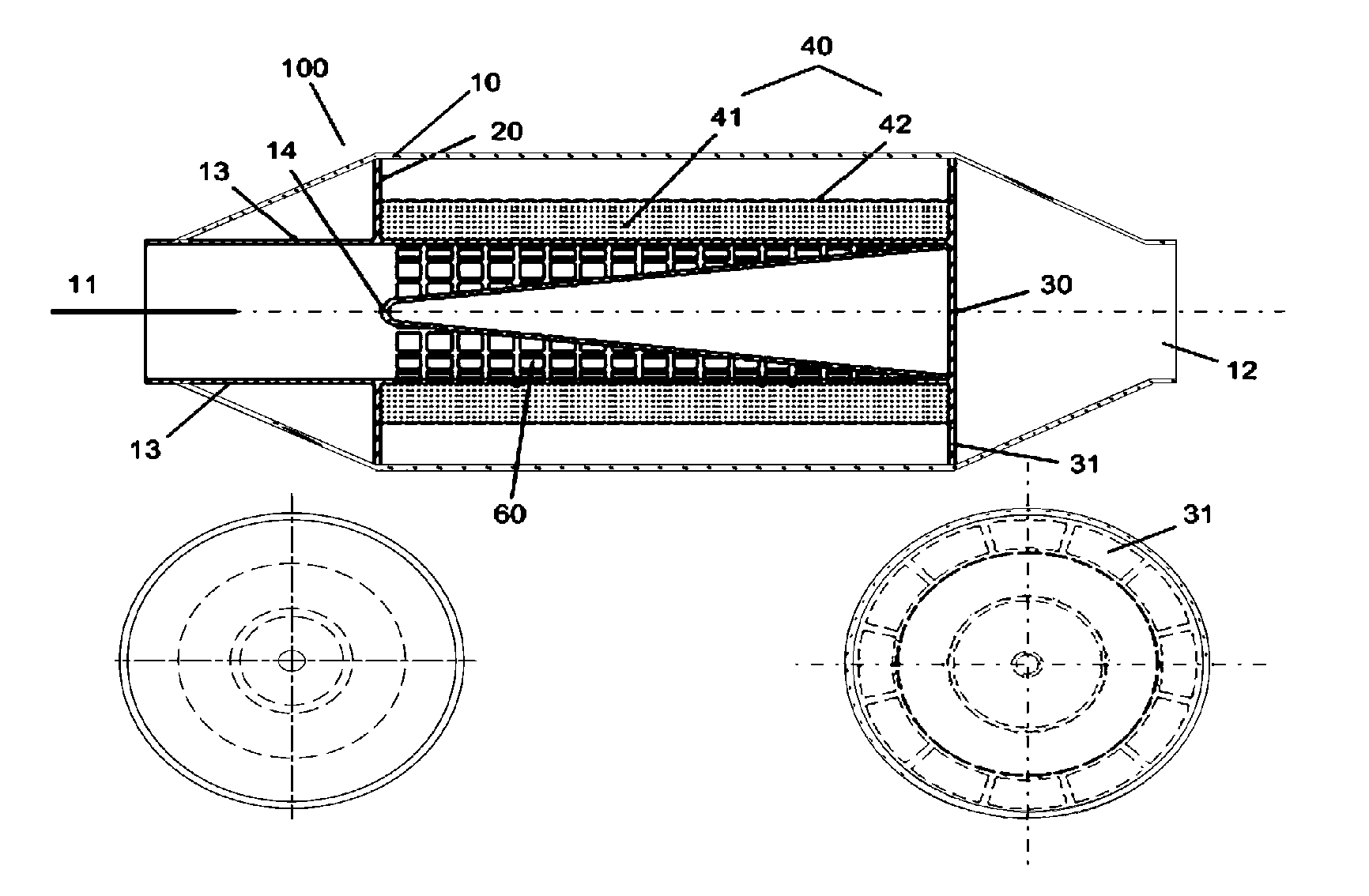
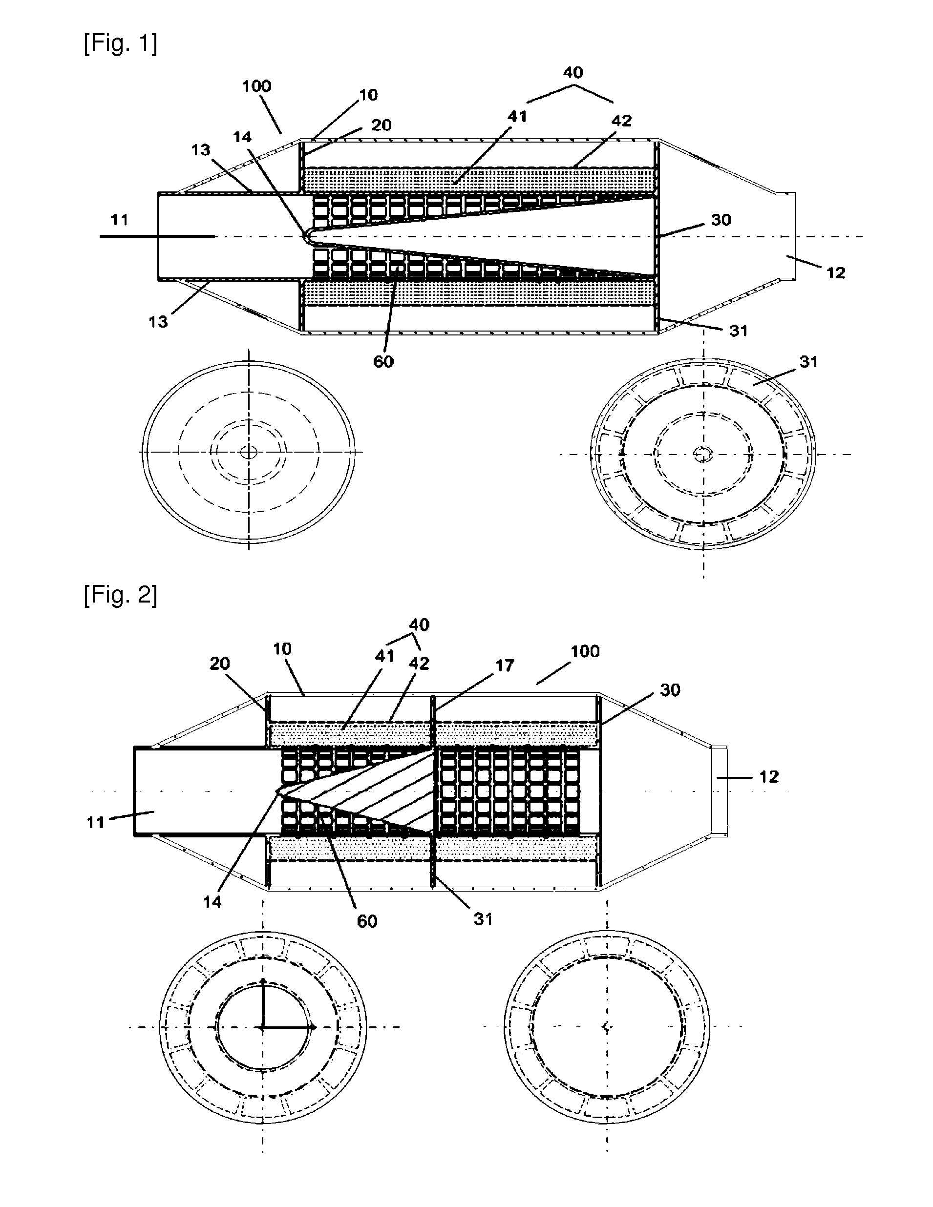
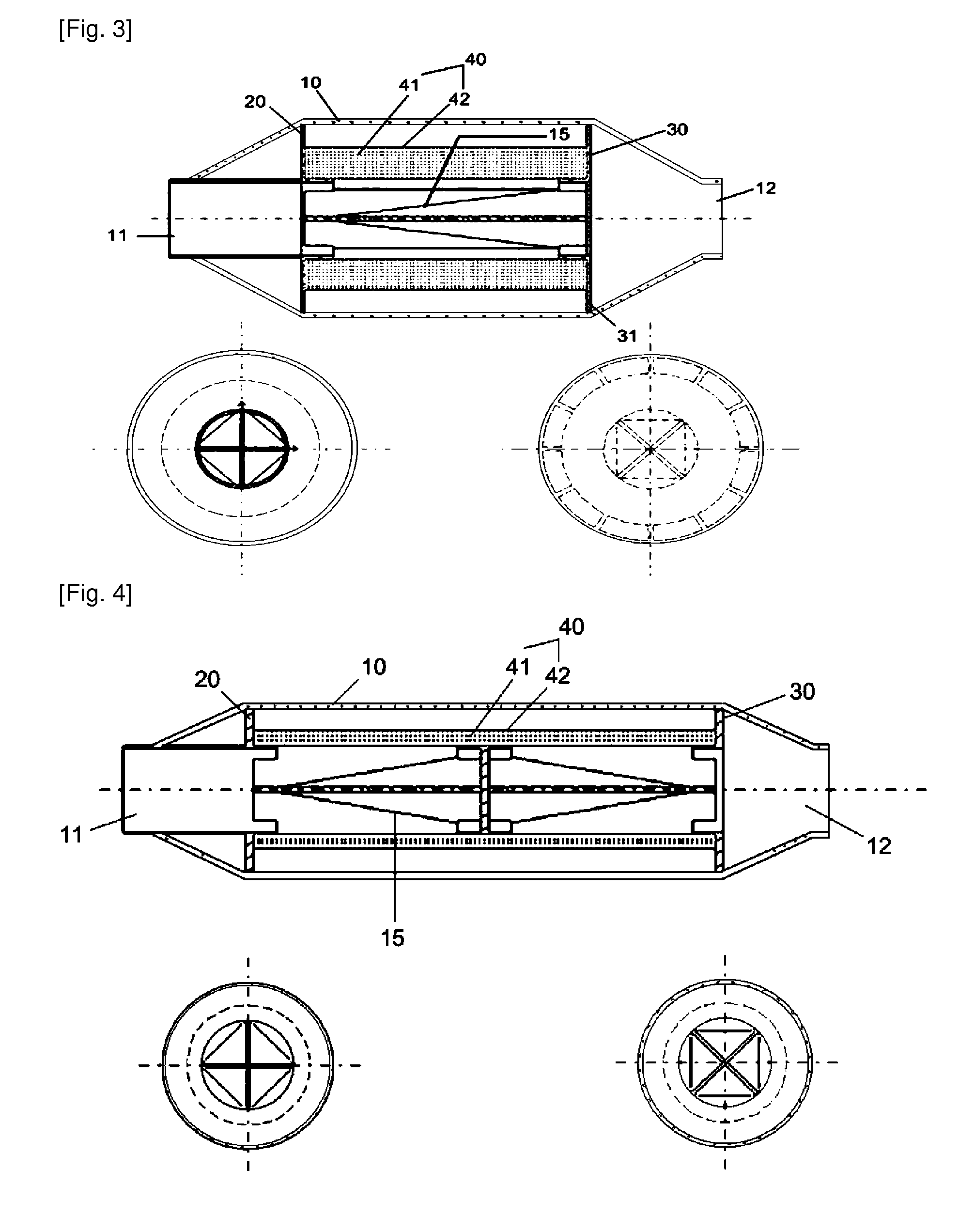
[0056]FIG. 1 is a section...


PUM

PropertyMeasurementUnit
porosity rateaaaaaaaaaa
durabilityaaaaaaaaaa

Abstract

A filter device for filtering automobile exhaust gas includes a case, front and rear support flanges mounted inside the case, and the filter member mounted between the front and rear support flanges. The front and rear support flanges are fixed vertically to the front and rear end portions of the filter member, respectively. The filter member includes a laminated or rolled-up metallic foam filter and a metallic mat or a jacket wrapping around the metallic foam filter. The porous pipe mounted inside the filter member is formed with a plurality of holes. The porous pipe is structured such that the width thereof decreases gradually towards the rear end portion or increase gradually towards the rear end portion, or the holes in the rear end portion are smaller, or a conical member is inserted in the inside space, or a pyramidal member is inserted in the inside space.

Description

TECHNICAL FIELD[0001]The present invention relates to a filter device for filtering automobile exhaust gas, in which a conical or pyramidal member is mounted inside a porous pipe through which the exhaust gas flows, thereby improving the flow of the exhaust gas and not creating a gradient in the flow rate to enable to uniformly collect particulate matter inside the porous pipe. The invention relates to a filter device for filtering automobile exhaust gas, in which a metallic foam filter mounted inside the filter member is wrapped around with a metallic mat to enable to preserve the original shape of the metallic foam filter to thereby improve the durability of the filter device. The invention relates to a filter device for filtering automobile exhaust gas, in which the filter member is divided into a plurality of filter regions by means of a partition, each of which is treated with various catalysts and then mounted inside a single filter member to thereby remove various gases from ...

Claims


Application Information

Patent Timeline
Patent Type & Authority Applications(United States)
IPC IPC(8): F01N3/035F01N3/01
CPCB01D46/0005B01D46/0027B01D46/0032B01D46/42B01D2275/30F01N2330/22F01N3/022F01N3/035F01N3/0821F01N3/2066F01N2240/20F01N3/0212Y02A50/20
Inventor KIM, HYUN TAE
Owner ALANTUM CORP
Why Eureka
Try Eureka