Cooling Module

a technology of cooling module and cooling chamber, which is applied in the direction of semiconductor devices for light sources, semiconductor/solid-state device details, lighting and heating apparatus, etc., can solve the problems of low cooling efficiency, loud noise, and still has drawbacks, and achieve the effect of reducing disturbances

Inactive Publication Date: 2011-05-19
SUNONWEALTH ELECTRIC MACHINE IND
View PDF3 Cites 19 Cited by
  • Summary
  • Abstract
  • Description
  • Claims
  • Application Information

AI Technical Summary

Benefits of technology

[0010]It is the primary objective of this invention to provide a cooling module that reduces a disturbed flow generated between a fan unit and a heat sink.

Problems solved by technology

Accordingly, drawbacks such as low cooling efficiency and loud noise are resulted.
However, the conventional cooling module 9 still has the drawbacks of the previously mentioned cooling module 8.

Method used


Image

  • Cooling Module
  • Cooling Module
  • Cooling Module

Examples


first embodiment

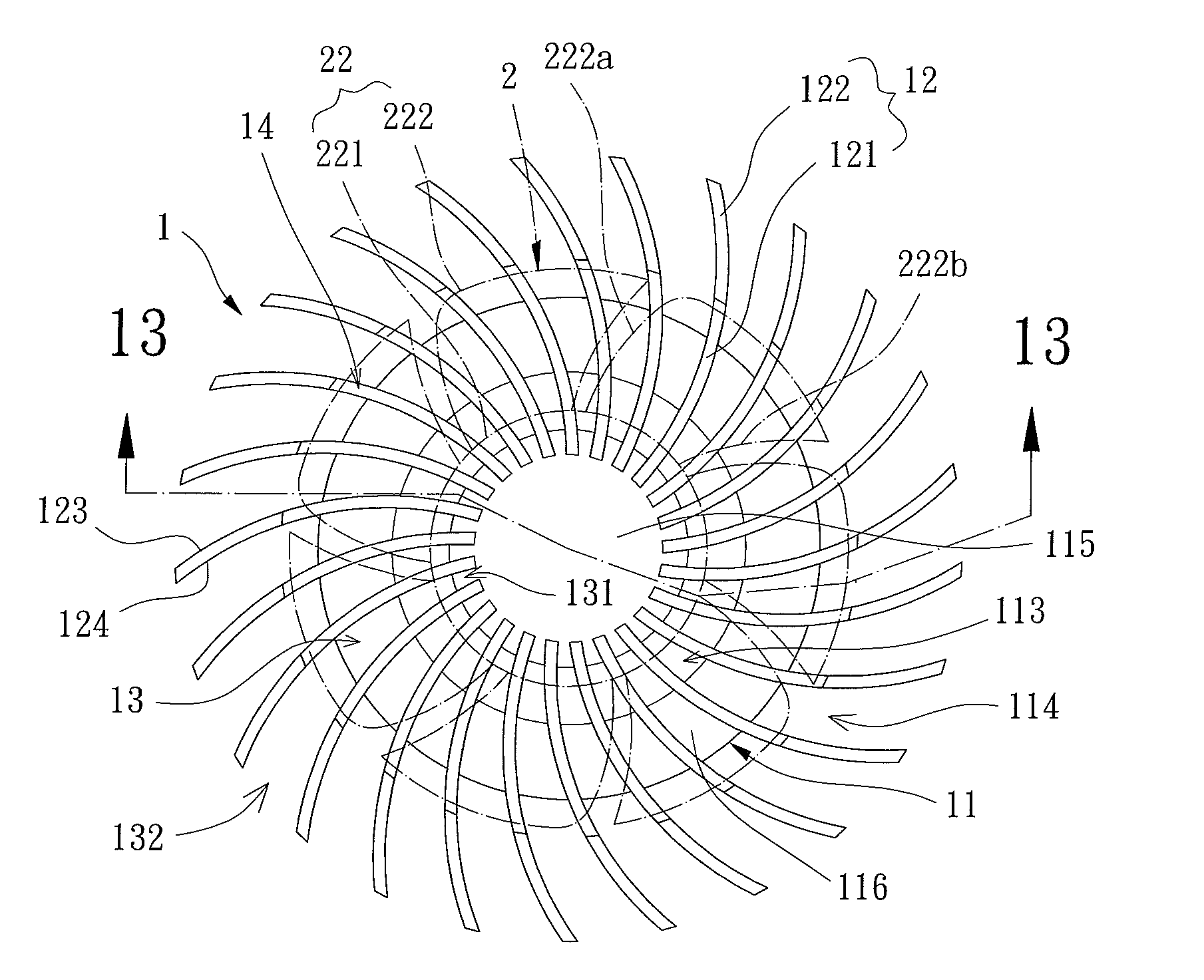
[0031]Referring to FIG. 5, a cooling module of the present invention is shown. The cooling module includes a heat sink 1 and a fan unit 2 and is used to lower the temperature of a heat-generating unit of an electronic product. The heat sink 1 is made of a material with high thermal conductivity, such as aluminum, copper, or magnesium-aluminum ally. The fan unit 2 is mounted on a side of the heat sink 1, and another side of the heat sink 1 connects with the heat generating unit indicative of the numeral “3,” with the heat generating unit 3 being a LED light in this embodiment. However, the heat generating unit 3 is not limited to the LED light; that is, a central processing unit or a chip set is also applicable.

[0032]The heat sink 1 has a base plate 11, a plurality of fins 12, and a plurality of air-guiding channels 13. The base plate 11 has a first surface 111 and a second surface 112 oppositely arranged at two sides of the base plate 11. Besides, the base plate 11 is preferably in ...

second embodiment

[0039]Accordingly, with the above-illustrated design of the base plate 11 of this second embodiment, the cool air entering the fan unit 2 can still straightly send to and contact with the base plate 11 for the heat exchange process. Moreover, areas of interfaces between the air-guiding channels 13 and the outside of the cooling module can be further increased for the inward and outward air flows to be exhausted fast.

[0040]Now turning to FIGS. 11 through 13, a cooling module of a third embodiment of the present invention is shown. In comparison with the base plate 11 of the second embodiment, the outlet 113 of the base plate 11 in the present embodiment is formed in a ring shape to separate the base plate 11 into a core portion 115 and an outer portion 116. The core portion 115 is arranged on the center of the base plate 11 and axially aligned with the hub 221 of the fan wheel 22. The outer portion 116 is radially sandwiched between the outlet 113 and the auxiliary outlet section 114...


PUM


Abstract

A cooling module is presented, which includes a heat sink and a fan unit. The heat sink provides a base plate and a plurality of fins, with an outlet extending through the base plate and the fins formed on a first surface of the base plate, and with a second surface of the base plate attached to a heat generating unit. The fan unit is rotatably mounted on the heat sink and aligned with the outlet. With the above-mentioned structure, an air-guiding channel is formed between any adjacent two of the fins and communicates with the outlet for a part of air outputted by the fan unit to be guided through the air guiding channels and exhausted by the outlet. Consequently, disturbed flows and wind noise are decreased while cooling efficiency is improved.

Description

BACKGROUND OF THE INVENTION[0001]1. Field of the Invention[0002]The present invention relates to a cooling module, particularly to a cooling module with reduced disturbed flow and low noise during operation.[0003]2. Description of the Related Art[0004]Referring to FIGS. 1 and 2, a conventional cooling module 8 including a heat sink 81 and an axial fan 82 is shown. The heat sink 81 has a base plate 811, a plurality of fins 812 and a plurality of air-guiding channels 813. The base plate 811 is preferably in a round shape, with the fins 812 evenly arranged along a rim of an upper surface of the base plate 811, radially extending, and defining a compartment 814 on the upper surface. Each air-guiding channel 813 is disposed between any two adjacent fins 812 and communicates with the compartment 814. The axial fan 82 is received in the compartment 814 and has a hub 821 and a plurality of blades 822 arranged around a lateral wall of the hub 821.[0005]In application of cooling electrical de...

Claims


Application Information

Patent Timeline
Patent Type & Authority Applications(United States)
IPC IPC(8): F28D15/00F28F7/00
CPCF21V29/02F21Y2101/02H01L23/467H01L2924/0002F21V29/80F21V29/77F21V29/677F21V29/74H01L2924/00F21Y2115/10
Inventor HORNG, ALEXFANG, I-LE
Owner SUNONWEALTH ELECTRIC MACHINE IND
Why Eureka
Try Eureka