Electric power supply system for vehicle

a technology for electric power supply and vehicle, applied in the direction of charging stations, electric propulsion mounting, transportation and packaging, etc., can solve the problems of limit to the overall capacity of batteries that can be loaded into a single vehicle, limit to the maximum mileage a vehicle can do per charging, limit to the overall capacity of batteries, etc., to achieve simple configuration, good stability, and reduce cost

Active Publication Date: 2011-05-19
PANASONIC CORP
View PDF12 Cites 15 Cited by
  • Summary
  • Abstract
  • Description
  • Claims
  • Application Information

AI Technical Summary

Benefits of technology

[0019]An electric power supply system for vehicle according to the present invention can get charging and powering done with good stability even if the vehicle's position has shifted significantly and even though the system has a simple configuration. As a result, a lighter system can be provided at a reduced cost. On top of that, the electri

Problems solved by technology

Meanwhile, considering the overall weight and cost of batteries, there is definitely a limit to the overall capacity of batteries that can be loaded into a single vehicle.
And that limit to the overall capacity of batteries directly leads to the maximum mileage a vehicle can do per charging.
However, since the resonant magnetic coupling method requires that k≠1 unlike the electromagnetic induction method in which k≈1, power cannot be transmitted with high efficiency unless inter-block impedance matching is kept achieved between the oscillation section and the power transmitting antenna and between the rectification section and the power receiving antenna.
In both of the system for charging and powering a running vehicle and the system for charging and powering a parked vehicle, the stability of transmission could be lost due to a relative positional shift between the power transmitting and receiving antennas.
Specifically, in the system for charging and powering a vehicle by resonant magnetic coupling, if the relativ

Method used


Image

  • Electric power supply system for vehicle
  • Electric power supply system for vehicle
  • Electric power supply system for vehicle

Examples


embodiment 1

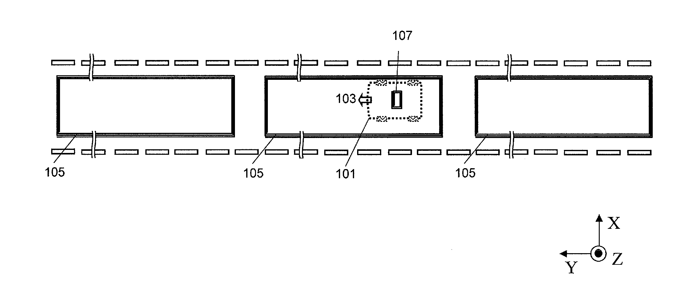
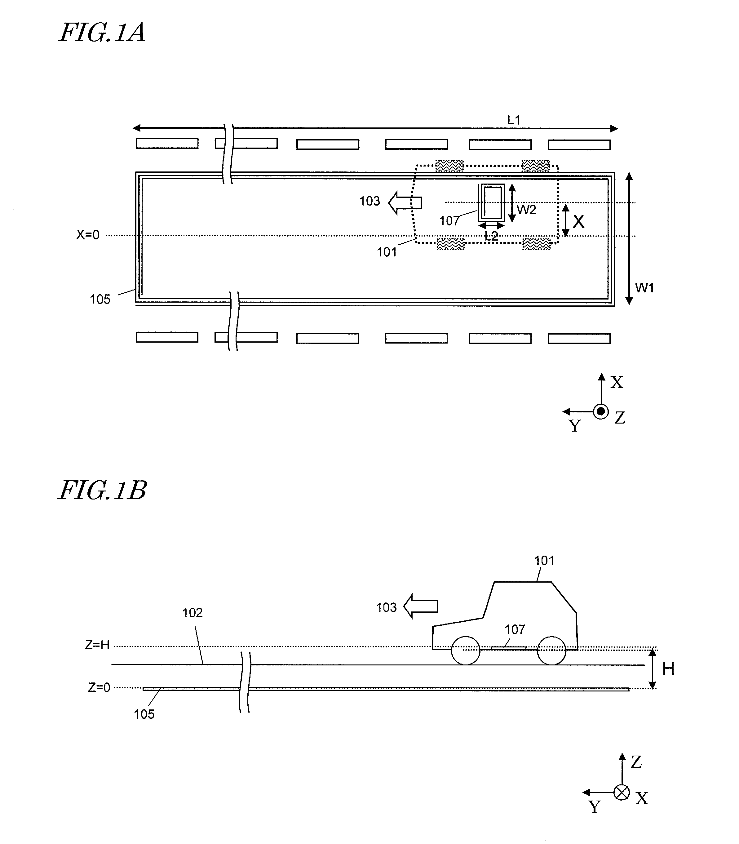
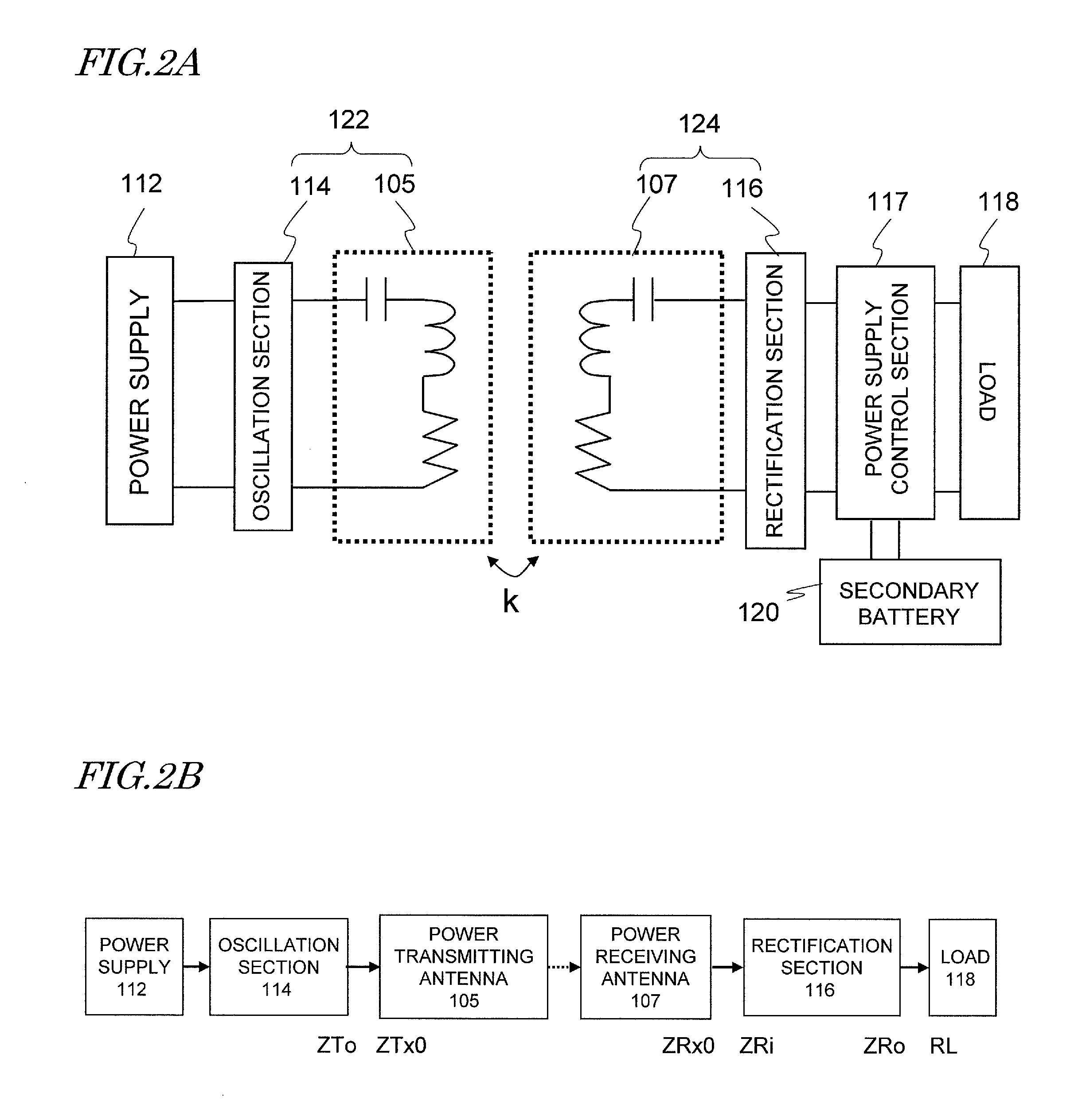
[0032]An Electric Power Supply System for Vehicle as a first specific preferred embodiment of the present invention is used as either an electric power supply system for the running vehicle for charging and / or powering a running vehicle or an electric power supply system for the parked vehicle for charging and / or powering a parked vehicle. As used herein, “to supply power” means “to charge” or “to power”. “To charge” means charging a secondary battery that is put in a vehicle and storing power to drive the vehicle, while “to power” means feeding electric power to a load (such as a driving electric motor) that is also built in the vehicle. An electric power supply system for vehicle according to this first preferred embodiment of the present invention includes a power transmitting antenna, which is provided on or under the ground, and a power receiving antenna, which is provided for the vehicle. These power transmitting and receiving antennas produce resonant magnetic coupling, there...

example 1

[0083]Hereinafter, specific examples of the present invention will be described.

[0084]To demonstrate the beneficial effect of the present invention, a specific example of the electric power supply system for vehicle was made to have the arrangement shown in FIGS. 1A and 1B and analyzed. In this example, the electric power supply system for vehicle satisfied W1=200 cm, L1=750 cm, and H=20 cm. The power transmitting antenna 105 and the power receiving antenna 107 were designed to have the same resonant frequency of 1 MHz. Also, the power transmitting and receiving antennas 105 and 107 were made of a Litz wire to reduce the resonator loss. On the condition that L2+W2=130 cm and W2>L2, three wireless transmitting sections with mutually different sets of L2 and W2 values (which will be referred to herein as “Examples 1a , 1b and 1c”, respectively) were analyzed. For the purpose of comparison, Comparative Examples 1a , 1b and 1c, satisfying W2≦L2, were also analyzed in the same way.

[0085]...


PUM


Abstract

To stabilize the transmission characteristic of an electric power supply system for vehicle even when the vehicle being charged and powered by it shifts horizontally, a power transmitting antenna, which is arranged on the ground, and a power receiving antenna, which is arranged at the bottom of the vehicle, set up resonances at substantially the same resonant frequency and produce magnetic resonant coupling between them. When the power receiving antenna enters the zone in which the power transmitting antenna is located, power is transmitted to the vehicle. By setting the width of the power receiving antenna as measured in the vehicle's width direction to be larger than the length of the power receiving antenna as measured in the vehicle's traveling direction, the transmission characteristic can be stabilized.

Description

[0001]This application claims priority under 35 USC §119(e) to U.S. Provisional Application No. 61 / 260,926 filed on Nov. 13, 2009, the entire contents of which are incorporated herein by reference.BACKGROUND OF THE INVENTION[0002]1. Field of the Invention[0003]The present invention relates to an electric power supply system for supplying energy to a vehicle from outside of it by a non-contact method.[0004]2. Description of the Related Art[0005]As an increasing number of people have been paying more and more attention to environmental issues these days, there have been growing expectations for electric vehicles to be driven with batteries and electric motors. Such an electric vehicle can naturally be charged and powered via cable connection. But people have been researching and developing wireless charging and powering techniques that adopt a non-contact method. Meanwhile, considering the overall weight and cost of batteries, there is definitely a limit to the overall capacity of bat...

Claims


Application Information

Patent Timeline
IPC IPC(8): B60K6/20B60L9/00B60K1/00
CPCB60L11/182H02J5/005Y02T90/122Y02T10/7005Y02T90/14H02J17/00Y02T10/7072B60L53/32H02J50/12B60L53/126H02J7/0068Y02T10/70Y02T90/12H02J50/40
Inventor KANNO, HIROSHI
Owner PANASONIC CORP
Why Eureka
Try Eureka