
Dissolved air flotation clarifier

a technology of clarifier and dissolved air, which is applied in the field of clarifier, can solve problems such as significant problems, and achieve the effect of increasing the efficiency of saturator and being easy to constru

Inactive Publication Date: 2011-05-19
RG DELAWARE
View PDF20 Cites 17 Cited by
  • Summary
  • Abstract
  • Description
  • Claims
  • Application Information

AI Technical Summary

Benefits of technology

The present invention provides a novel and unobvious dissolved air flotation clarifier that can operate at high flow rates without encountering entrained micro-bubbles in the effluent. It also prevents or reduces the entrainment of micro-bubbles in the effluent without requiring a higher false bottom construction. The clarifier includes a housing with an inlet for receiving liquid to be clarified, a reaction zone, a clarification zone, and an effluent channel. The clarification zone has at least one saturated water distributor and at least one dissolved air flotation nozzle operably connected to the at least one saturated water distributor to receive saturated water from the at least one saturated water distributor. The dissolved air flotation nozzle is configured to release micro-bubbles from the saturated water so that the micro-bubbles can mix with the liquid to be clarified to remove impurities from the liquid to be clarified. The clarifier also includes at least one recycle header for removing a portion of liquid from the clarification zone. The invention provides a method of clarifying a liquid with the dissolved air flotation clarifier.

Problems solved by technology

A significant problem has been encountered by a number of previously known DAF clarifiers when the flow rate is increased above 8 to 10 gpm / sq.ft.

Method used


Image

  • Dissolved air flotation clarifier
  • Dissolved air flotation clarifier
  • Dissolved air flotation clarifier

Examples


Embodiment Construction

[0025]The preferred forms of the invention will now be described with reference to FIGS. 3-7. The appended claims are not limited to the preferred forms and no term and / or phrase used herein is to be given a meaning other than its ordinary meaning unless it is expressly stated otherwise.

FIGS. 3 Through 5

[0026]Referring to FIGS. 3 to 5, a preferred form of DAF clarification system includes a flocculator G located upstream of clarifier H. The flocculator G may contain one or more flocculation zones (two flocculation zones 15 are shown in FIG. 4). It should be noted that any suitable flocculator can be used. A coagulant may be added to the liquid to be filtered prior to entry into the flocculator G to destabilize the colloidal particles which facilitates their agglomeration in the flocculator G. Preferably, the clarifier H includes a housing 17 forming an inlet chamber or zone I, a reaction chamber or zone J, a clarification chamber or zone K and an effluent channel L. As used herein, ...


PUM

PropertyMeasurementUnit
angleaaaaaaaaaa
widthaaaaaaaaaa
flocculationaaaaaaaaaa

Abstract

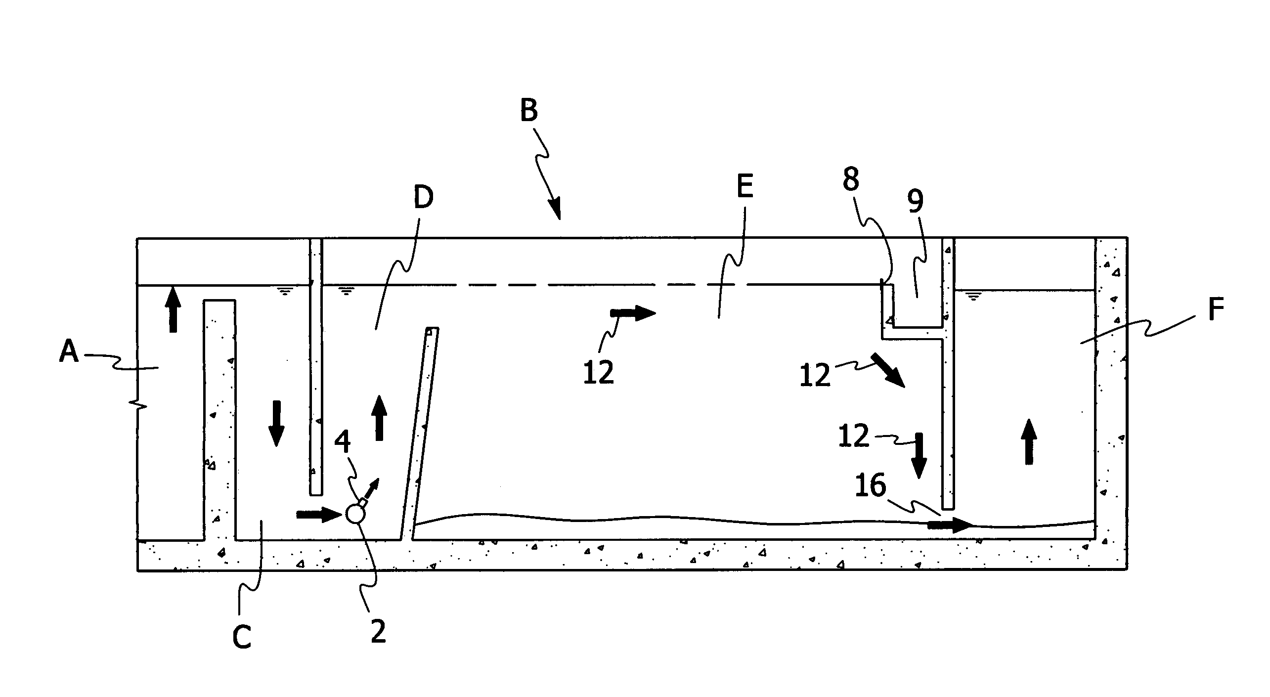
A dissolved air flotation clarifier for removing impurities from a liquid to be clarified. The dissolved air flotation clarifier includes a housing having an inlet for receiving a liquid to be clarified. The housing further includes a reaction zone, a clarification zone and an effluent channel. The reaction zone has at least one saturated water distributor and at least one dissolved air flotation nozzle operably connected to the at least one saturated water distributor to receive saturated water from the at least one saturated water distributor. The dissolved air flotation nozzle is configured to release micro-bubbles from a saturated water so that the micro-bubbles can mix with the liquid to be clarified to remove impurities from the liquid to be clarified. The clarification zone includes a flow control member for controlling the flow of the mixture of micro-bubbles and liquid in the clarification zone to ensure that the area surrounding the inlet to the effluent channel has little or no micro-bubbles to prevent or significantly reduce micro-bubbles from becoming entrained in a clarified liquid passing through the effluent channel.

Description

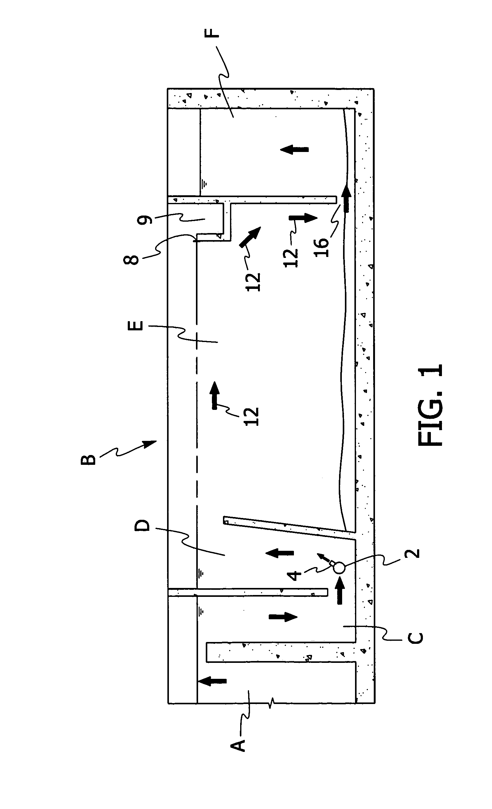
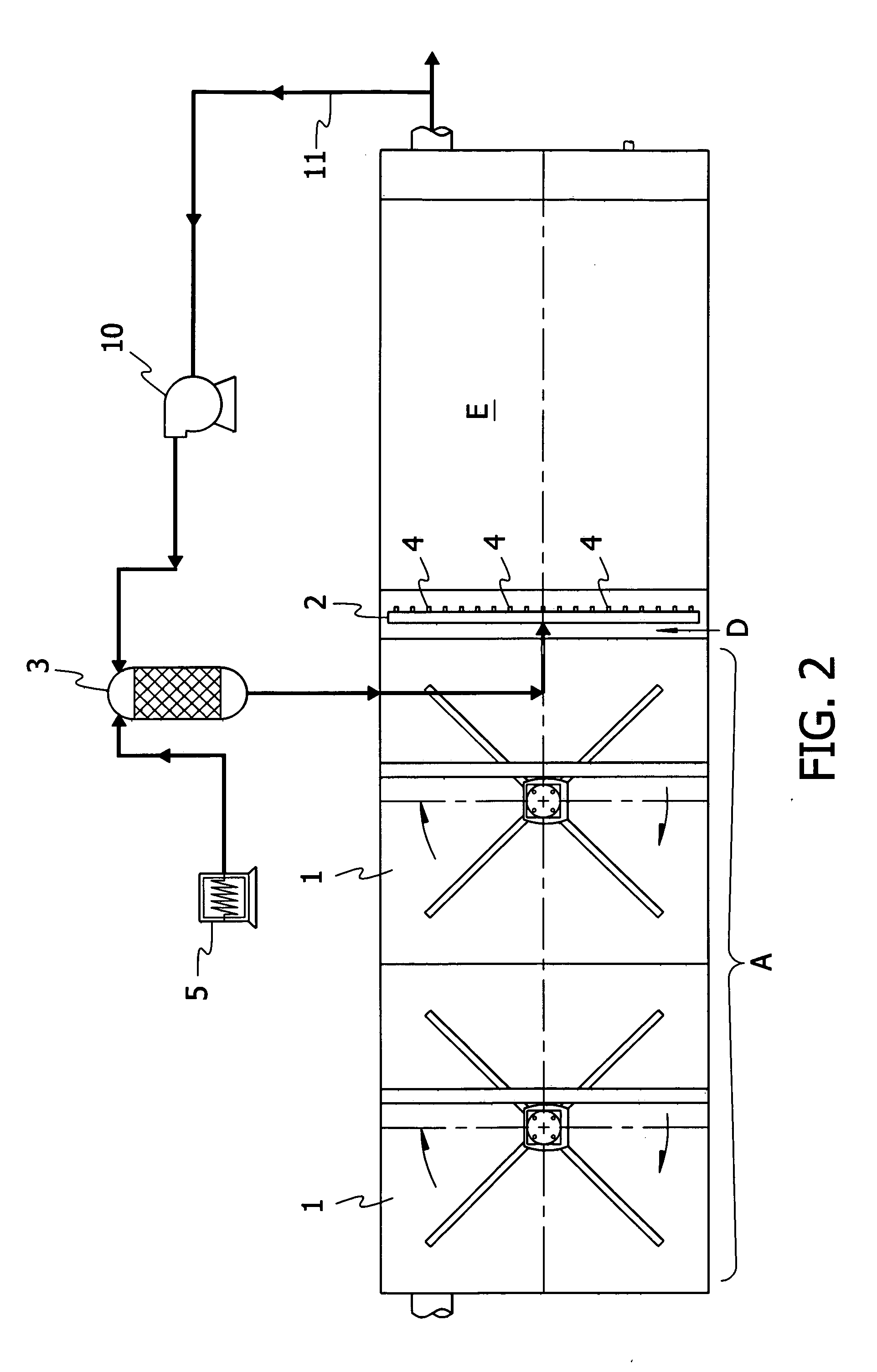
FIELD OF THE INVENTION[0001]The present invention is directed to a clarifier for removing impurities from a liquid including but not limited to water and / or wastewater. More specifically, the present invention is directed to a clarifier that employs dissolved air flotation to remove impurities from a liquid. The clarifier of the present invention may be used with one or more flocculators upstream of the clarifier. The clarifier of the present invention may also be used with one or more additional filter systems downstream of the clarifier including but not limited to filters using granular media or membranes.BACKGROUND OF THE INVENTION[0002]Clarifiers using dissolved air flotation (DAF) to remove impurities from water or wastewater are known. As used herein, the term clarifier includes any device that removes impurities from a liquid including but not limited to roughing filters or polishing filters.[0003]A typical prior art DAF basin is illustrated in FIGS. 1 and 2. A flocculator A...

Claims


Application Information

Patent Timeline
Patent Type & Authority Applications(United States)
IPC IPC(8): B01D17/035C02F1/24B03D1/00
CPCB01D17/0205B03D1/1431B03D1/1493B03D1/1412B03D1/1475B03D1/028C02F1/24
Inventor ROBERTS, R. LEEADDISON, MARK KEVIN
Owner RG DELAWARE
Learn More