
Vacuum Oven

a vacuum oven and oven body technology, applied in the field of vacuum ovens, can solve the problems of different surface finishes, hard spots or residual stress in metals, and different surface finishes of ovens or furnaces, and achieve the effect of more consistent and regular radiation fields

Active Publication Date: 2011-05-19
IBEX DENTAL TECH
View PDF27 Cites 18 Cited by
  • Summary
  • Abstract
  • Description
  • Claims
  • Application Information

AI Technical Summary

Problems solved by technology

One of the problems that has arisen in connection with vacuum ovens or furnaces is that of heat distribution in the oven.
Inconsistent and irregular radiation fields can result in hard spots or residual stress in metals, different surface finishes and color variations in ceramics and porcelains, and a myriad of other issues in more exotic materials.

Method used


Image

  • Vacuum Oven
  • Vacuum Oven
  • Vacuum Oven

Examples


Embodiment Construction

[0013]While the making and using of various embodiments of the present invention are discussed in detail below, it should be appreciated that the present invention provides many applicable inventive concepts which can be embodied in a wide variety of specific contexts. The specific embodiments discussed herein are merely illustrative of specific ways to make and use the invention, and do not delimit the scope of the present invention.

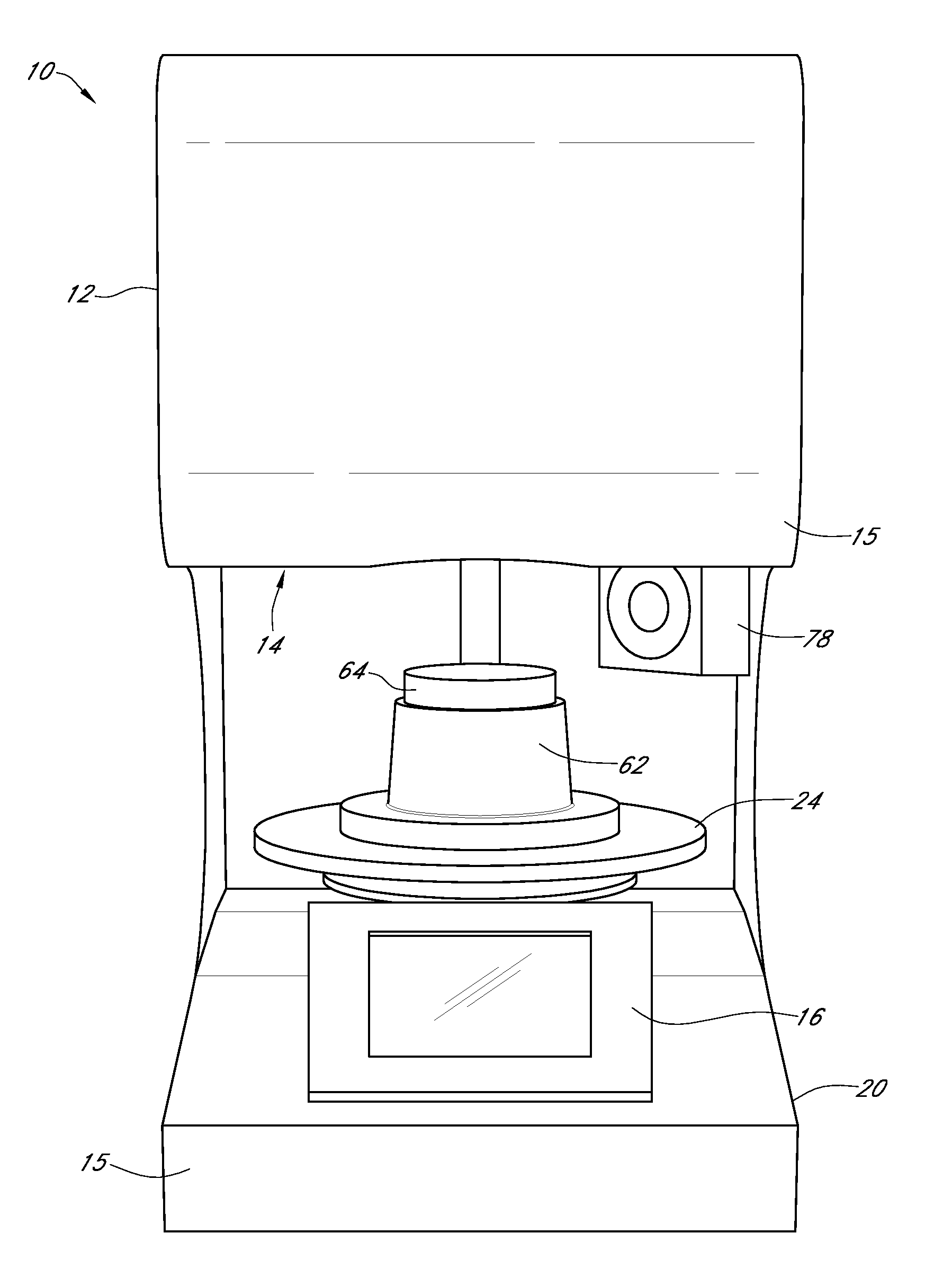
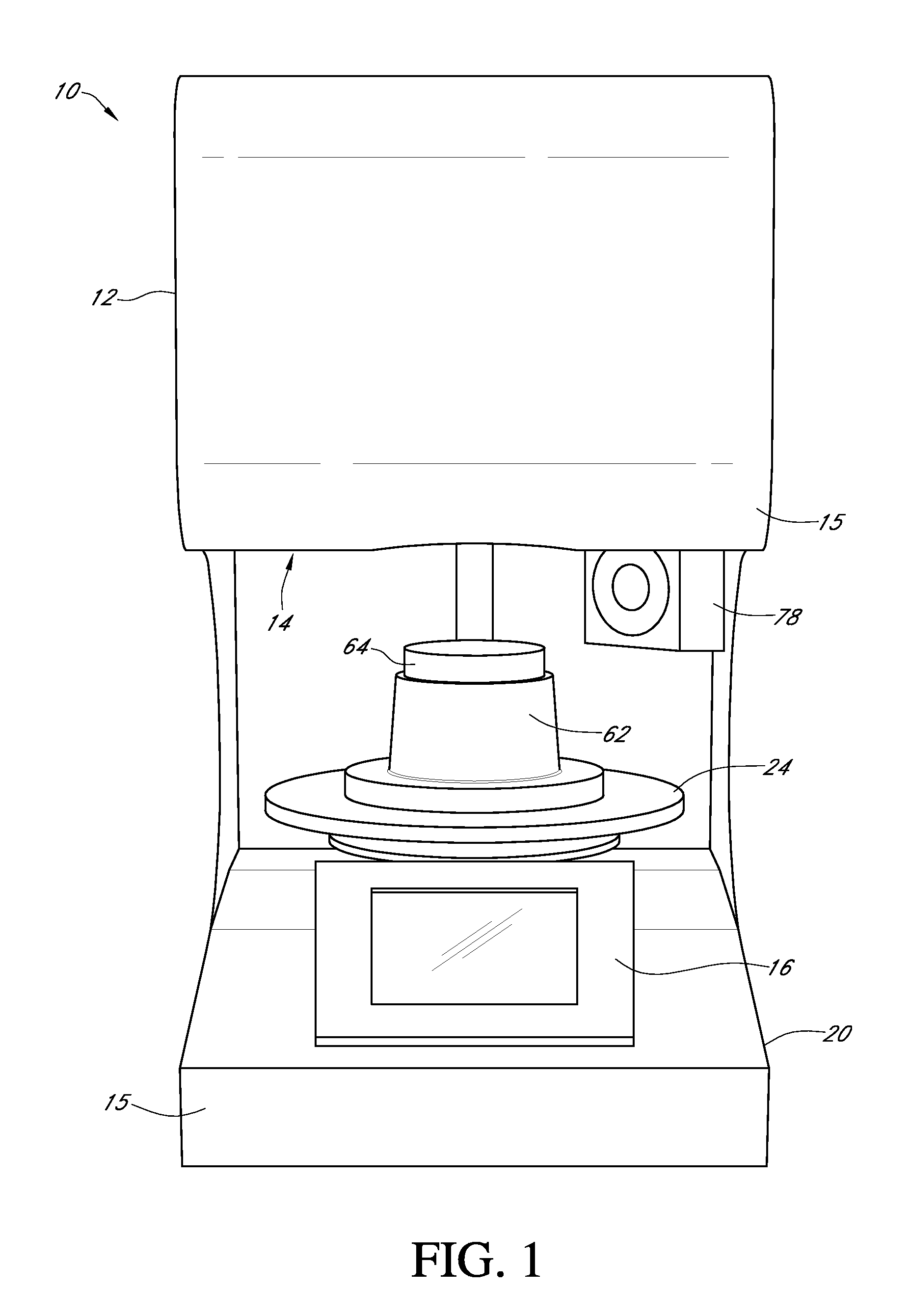
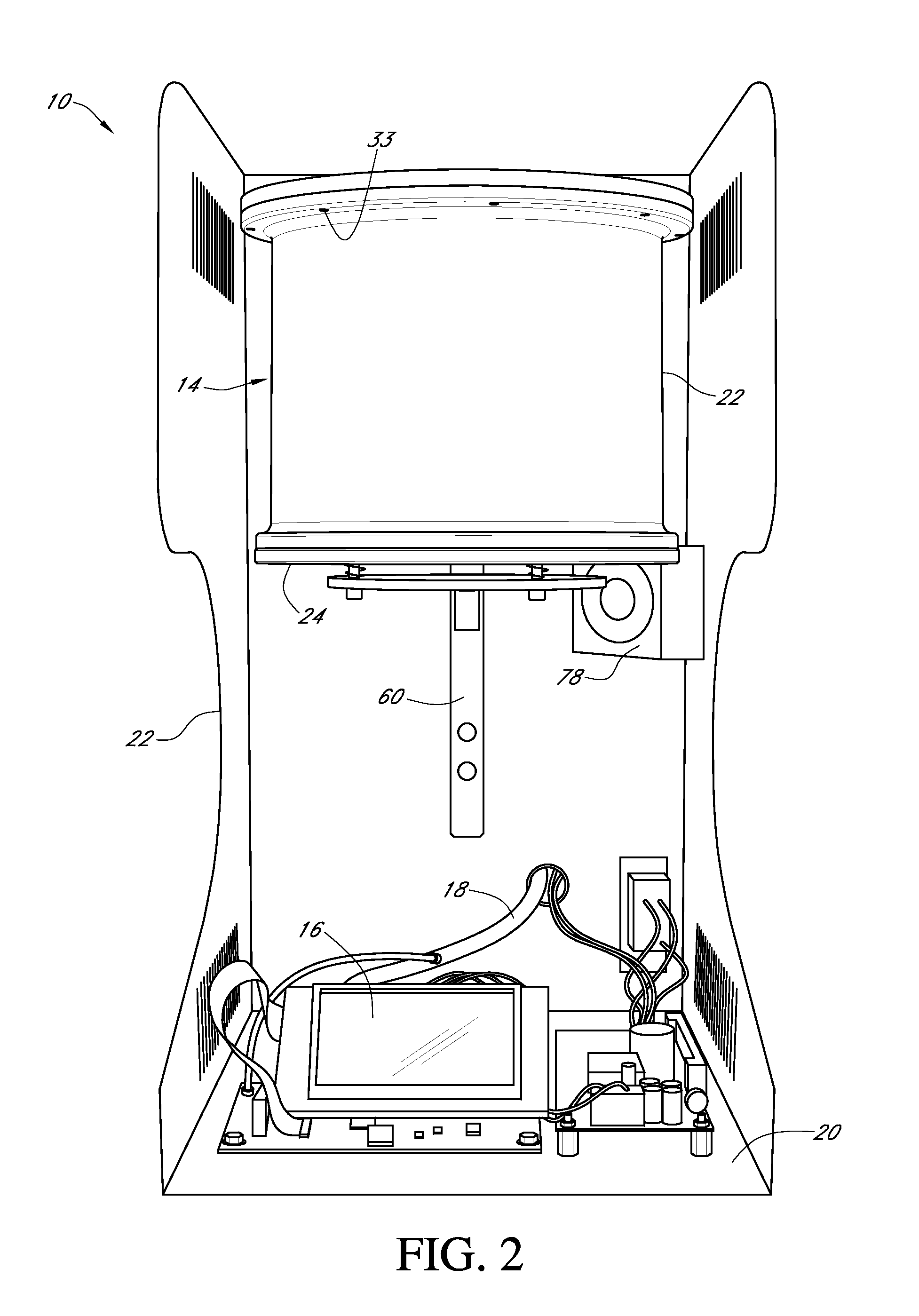
[0014]Referring to FIGS. 1-6, therein is depicted a vacuum oven that is schematically illustrated and generally designated 10. A body 12, which includes panels 15 (cutaway or removed in FIG. 2), supports a vacuum chamber assembly 14, which is depicted as a two-part, bottom loading vacuum chamber assembly. A control panel 16 with display and various supporting electronics 18 are mounted to a base 20 of the body 12 and, by way of internal communication through the body 12, located in electronic communication with the vacuum chamber assembly 14. The vacuum...


PUM


Abstract

A vacuum oven or vacuum furnace is disclosed having a heat distribution sleeve that conforms to the shape of an interior heating chamber. The heat distribution sleeve may be of generally annular shape, like a ring, and located in a substantially regularly spaced and offset relationship from a heating element located within walls adjacent the interior heating chamber. The heat distribution sleeve includes a thermal conductive material which absorbs and re-radiates heat emitted from the heating element, thereby providing more consistent and regular radiation fields for heating treating a work piece that is loaded on a work holding tray and, upon the vacuum oven being in an operational position, the work piece is located within the furnace chamber.

Description

PRIORITY STATEMENT & CROSS-REFERENCE TO RELATED APPLICATIONS[0001]This application claims priority from co-pending U.S. Patent Application No. 61 / 262,318, entitled “Vacuum Oven” and filed on Nov. 18, 2009, in the names of Daniel F. Serrago and James D. Emmons; which is hereby incorporated by reference for all purposes.TECHNICAL FIELD OF THE INVENTION[0002]This invention relates, in general, to temperature distribution and regulation and, in particular, to a vacuum oven adapted for heat treating a work piece positioned therein.BACKGROUND OF THE INVENTION[0003]One of the problems that has arisen in connection with vacuum ovens or furnaces is that of heat distribution in the oven. That is, all of the work area doesn't see a similar radiation field. Inconsistent and irregular radiation fields can result in hard spots or residual stress in metals, different surface finishes and color variations in ceramics and porcelains, and a myriad of other issues in more exotic materials. These incon...

Claims


Application Information

Patent Timeline
Patent Type & Authority Applications(United States)
IPC IPC(8): A21B1/22
CPCF27B17/025F27B5/04F27B5/08F27B5/18F27B5/14
Inventor SERRAGO, DANIEL F.EMMONS, JAMES D.
Owner IBEX DENTAL TECH
Learn More