Method and apparatus for reducing coupled noise influence in touch screen controllers

a touch screen controller and coupled noise technology, applied in the direction of instruments, computing, electric digital data processing, etc., can solve the problems of affecting the capacitance measured by affecting the accuracy of the touch screen controller, and errors in the reported touch or the location of the touch, so as to reduce the influence of noise produced

Active Publication Date: 2011-05-19
PARADE TECH
View PDF30 Cites 170 Cited by
  • Summary
  • Abstract
  • Description
  • Claims
  • Application Information

AI Technical Summary

Benefits of technology

[0009]There has been provided a method and apparatus for reducing the influence of noise produced in a display (e.g. an LCD) on touch screens and their associated controllers which employ a noise detector for producing an output in response to an edge of recognized noise; and a state machine responsive to the output for synchronizing the generation and measurement of the signals used to measure the capacitances of the touch screen and produce an output.
[0015]In an exemplary embodiment there is provided an apparatus for reducing noise influence on capacitance data measured by a touch screen controller comprising a bus including a bus connection switch adapted to be responsively coupled to one or more Tx and Rx lines in a touch panel coupled to an LCD display; a programmable gain amplifier coupled to the bus connection switch; a threshold comparator coupled to the programmable gain amplifier or PGA responsive to positive and negative going noise pulses for producing a corresponding output indicative thereof; a synchronization noise multiplexor responsively coupled to an output of the threshold comparator and a logic synchronization signal for producing a synchronization event signal; a programmable look up table or LUT for storing a plurality of programmed conditions, said LUT having first and second inputs being respectively responsive to the synchronization signal and programmable delay line for producing an output in accordance with the programmed conditions; a programmable delay line responsively coupled to the synchronization signal for presenting a delayed form of the synchronization signal; an interval counter responsive to the synchronization event signal for counting synchronization intervals; an interval discriminator responsive to the interval counter for discriminating an interval between the edges of successive synchronization event signals; and an intervals FIFO buffer or FIFO coupled to the interval counter for storing intervals between successive synchronization event signal edges.

Problems solved by technology

Unfortunately, the normal operation of the LCD often produces electrical noise which adversely affects or influences the capacitances measured by the touch screen controller.
This noise can interfere with or unduly influence the capacitances measured by the touch screen controller thereby resulting in errors in reported touches or locations of touches.
These tend to be expensive and difficult to implement, because they require complex circuitry and high processor overhead and speeds.
Another solution has been to increase the Tx signal strength in the touch screen controller, but this decreases battery life.
Other exemplary software and hardware approaches currently available have had mixed results, and each exhibit disadvantages in terms of cost, implementation and performance.
These approaches are direct and can be effective, but they often increase cost.
More importantly these methods result in a thicker, more bulky touch screen device which may be commercially unattractive, because users seem to prefer slim, light weight devices.
Other techniques employ specialized firmware, which adds cost and reduces the competitiveness of the resulting system.

Method used


Image

  • Method and apparatus for reducing coupled noise influence in touch screen controllers
  • Method and apparatus for reducing coupled noise influence in touch screen controllers
  • Method and apparatus for reducing coupled noise influence in touch screen controllers

Examples


Embodiment Construction

[0035]A method and apparatus for reducing the influence of display (e.g., an LCD) noise in capacitive sensed touch screens may be provided. In one embodiment a synchronization technique is employed to implement noise reduction. In another embodiment synchronization may be combined with a noise blanking feature. In yet another embodiment, a variety of sensing arrangements are featured. Another embodiment employs a delay line for restoring lost or noise damaged signal. In still another embodiment, filtering techniques are described. These techniques may be used alone or in selected combinations which enhance performance.

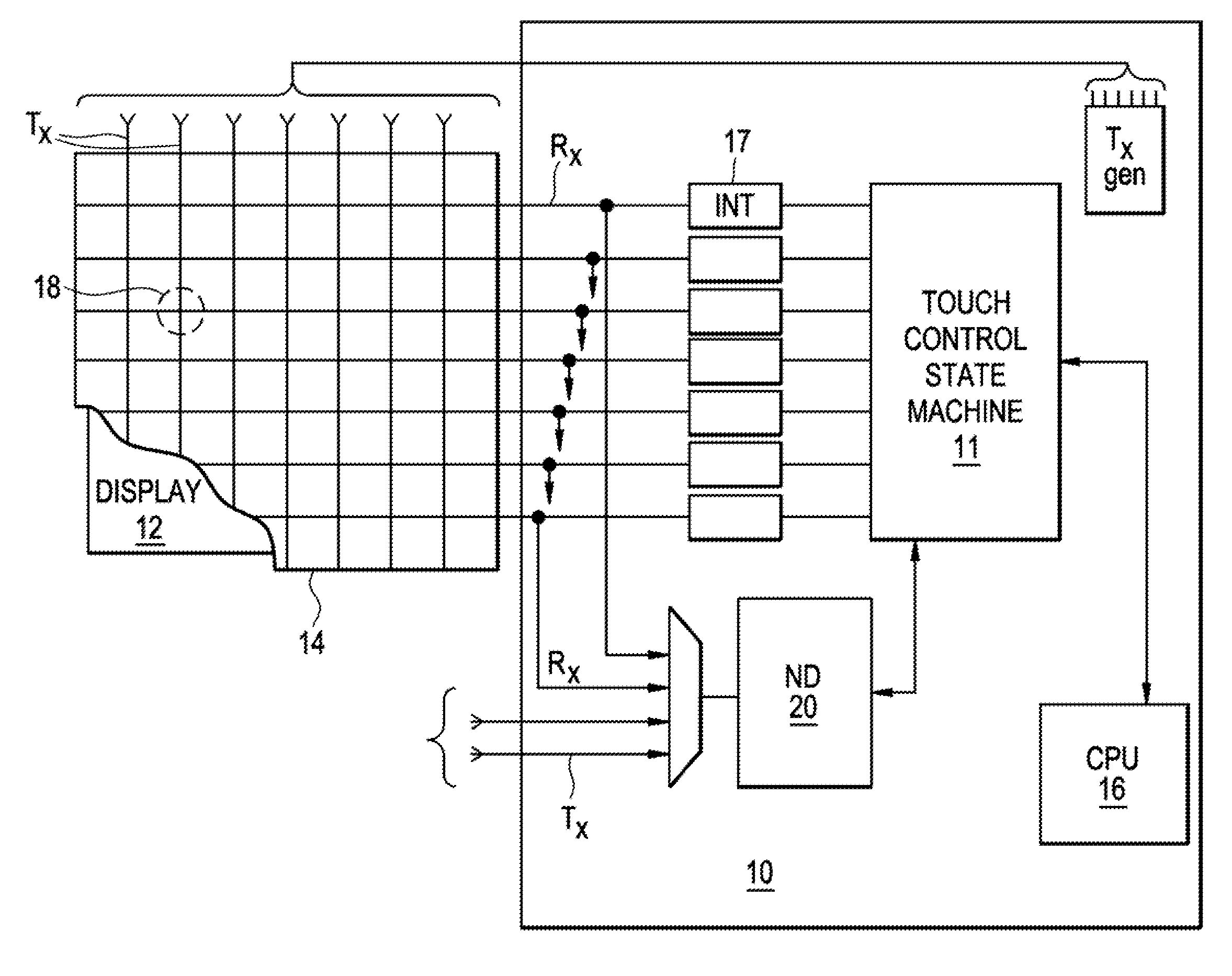
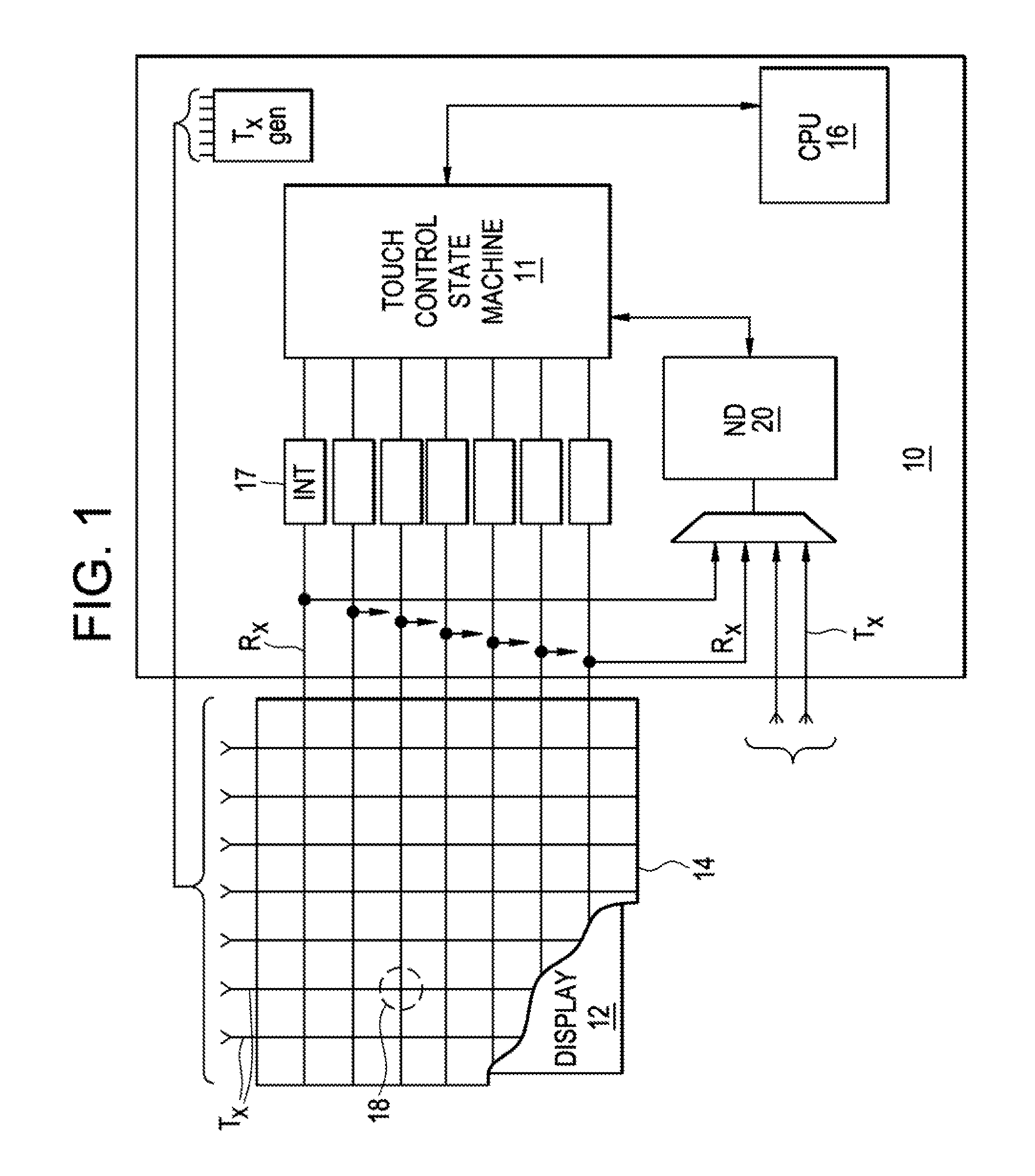
[0036]FIG. 1 illustrates a generalized illustration of a touch screen coupled with a touch screen controller 10 incorporating a noise reduction system. The touch screen controller 10 is coupled to a transparent touch screen or panel 14. A display 12 is positioned behind the touch screen panel 14, such that the display 12 produces an image which may be viewed through th...


PUM


Abstract

A method and apparatus for reducing influence of noise for touch screen controllers employing noise listening synchronization, delay lines, filtering and sensing selected touch screen electrodes.

Description

RELATED APPLICATIONS[0001]This application claims the benefit of U.S. Provisional Application Nos. 61 / 253,142 and 61 / 323,907 filed Oct. 20, 2009.TECHNICAL FIELD[0002]The present invention relates generally to devices employing a display coupled with a touch screen interface and, more particularly to methods and apparatus for limiting the influence of display generated noise.BACKGROUND[0003]Touch screens are user interface devices employed with electronic visual displays that may detect the presence of a touch on or in the vicinity of a display area of a touch screen or panel. A known touch screen user interface employs transparent conductive electrodes composed indium tin oxide or ITO which overlay the display such as an LCD or other suitable display device.[0004]The term touch screen generally refers to a transparent panel overlaying an display, such as an LCD, which may be touched with a finger, hand or stylus to produce an output signal or indication, and may also include so-call...

Claims


Application Information

Patent Timeline
Patent Type & Authority Applications(United States)
IPC IPC(8): G06F3/041
CPCG06F3/0418G02F1/13338G06F3/044G06F3/0446G06F3/04182G06F3/0445G06F3/04184
Inventor KREMIN, VICTORKONOVALOV, ANTON
Owner PARADE TECH
Why Eureka
Try Eureka