LED variable light source

a variable light source and led light technology, applied in the field of light stimulators, can solve the problems of wasting 90% of the power generated by incandescent or arc lamps and the power delivered to each target, and the known instrumentation that includes such visual stimulators for carrying out electroretinograms, electro-oculograms, and other visually evoked examinations is further known to be bulky and expensive, and achieves the effect of low heat emission

Inactive Publication Date: 2011-05-19
THE RES FOUND OF STATE UNIV OF NEW YORK
View PDF4 Cites 22 Cited by
  • Summary
  • Abstract
  • Description
  • Claims
  • Application Information

AI Technical Summary

Benefits of technology

[0012]To that end, the SLD-based light source of the invention results in a LED variable light source for use as a visual stimulator, such as those used to conduct retinal examinations, e.g., electroretinograms, electro-oculograms, and other visually evoked examinations, constructed in fully electronic and compact form to operate more simply and with more flexibility known light stimulators. The novel LED variable light source of the invention is expected to be ideal for use by individuals and institutions that conduct research and / or retinal examinations with small animals, light sensitive cells (for example, a retina of a human eye) and systems and devices for implementing same. The novel LED variable light source or light stimulator of the invention is controlled by at least two modes. In the first mode the light is controlled by changing the duty cycle of a pulsed signal (>1 MHz) driving the LED; in the second mode it is controlled by a DC source or current or voltage, and is continually driven by the same DC source. Moreover, by virtue of the compact size, electronic control of flash parameters (flash duration, color and intensity) and power efficiency (low heat emission) the light source can be set near the subject to directly irradiate the subject's eye, circumventing the use of optical devices, shutters (and associated light losses) required to direct the light beam to the retina from a remote source.

Problems solved by technology

Known instrumentation that includes such known visual stimulators for carrying out electroretinograms, electro-oculograms, and other visually evoked examinations are further known to be bulky and expensive.
These restrictions yield losses in terms of the power generated by the incandescent or arc lamps and the power delivered to each target.
Put in other words, 90% of the power is wasted by this means.
Additional power loss results from the inefficacy of the timing mechanism.
Thus, a large amount of power is wasted by this means.
Incandescent and arc lamps are not designed to operate in pulsed regimes.
Another option is using the new generation of ‘pulsed’ arc lamps, however their cost is several-fold higher than the LED solution we propose and also require color filter option for their operation.
Pulsed-LED devices, however, have limitations.
A second limitation at dim levels regards the step-wise rather than continuous regulation of light intensity.

Method used


Image

  • LED variable light source
  • LED variable light source
  • LED variable light source

Examples


Embodiment Construction

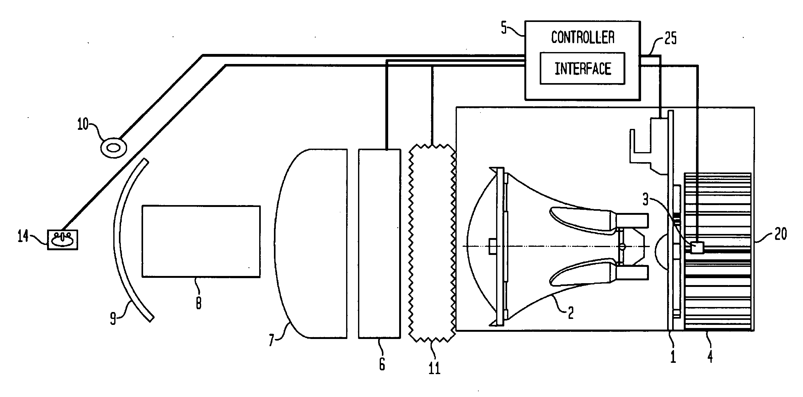
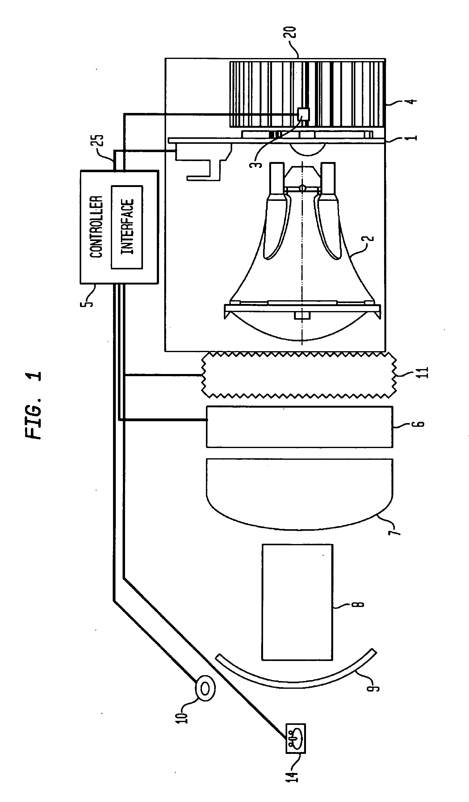
[0027]A LED variable light source, visual stimulator including a novel LED variable light source, and method of conducting a retinal examination by use of the novel LED variable light source are set forth and described herein for the purpose of conveying the broad inventive concepts. The drawings and descriptions provided are not meant to limit the scope and spirit of the invention in any way. To that end, reference will now be made in detail to the present invention, examples of which are illustrated in the accompanying drawings, wherein like reference numerals refer to like elements throughout.

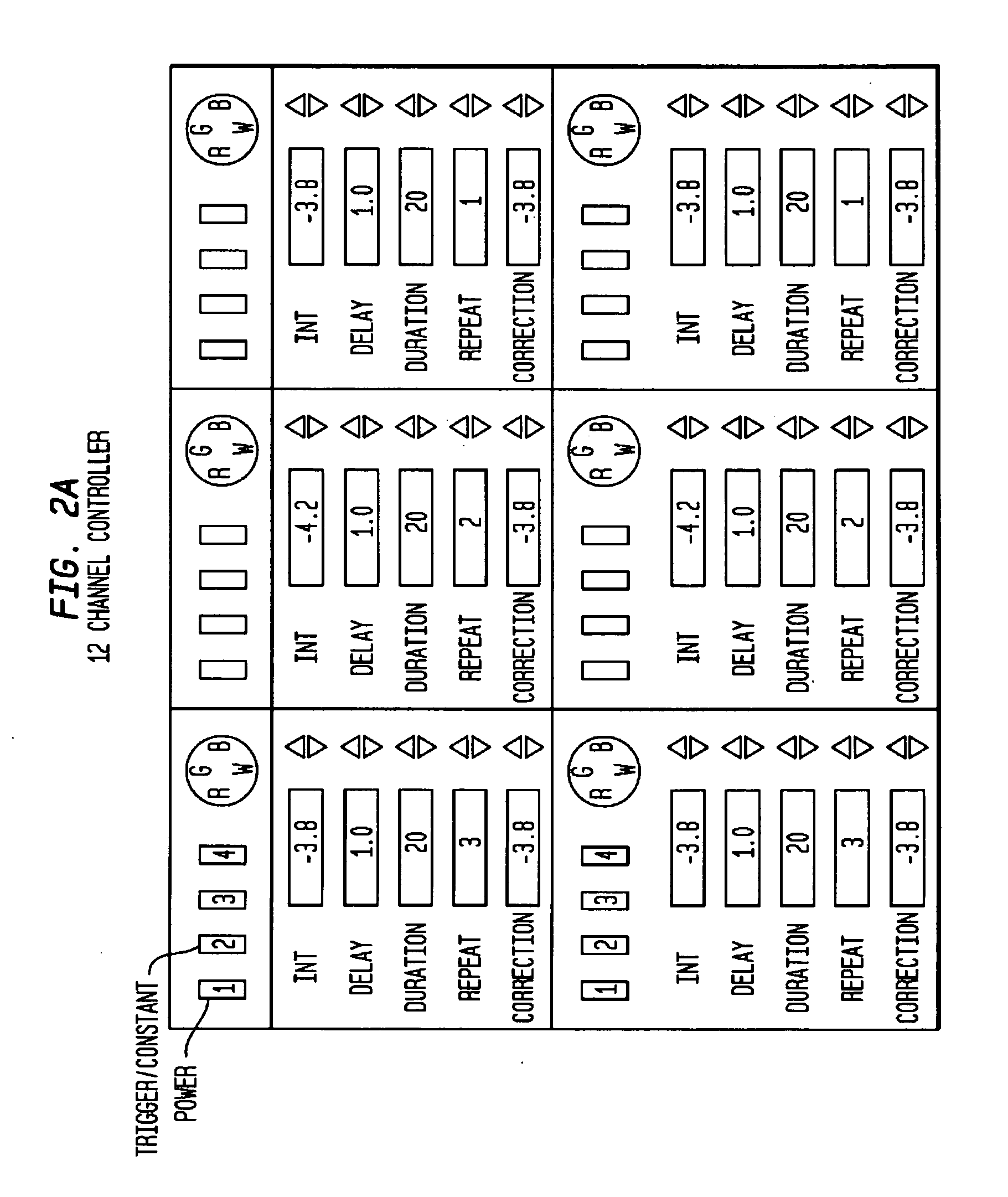
[0028]Via a graphics display on the computer monitor or via settings on a controller (controller box), the user sets the values for the light parameters. The term run as used herein represents a sequence of flashes. Each run is triggered by an input TTL pulse. A plurality of independent flashes can be presented in each run. For example, twelve independent LED units can source twelve differen...


PUM


Abstract

An LED variable light source of this invention includes a super luminescent LED for generating a continuous light signal having a logarithmically controllable light intensity maintainable over a broad spectral range. The LED variable light source also includes a light lens for receiving and focusing the generated continuous light signal and a controller for controlling the light signal's intensity and frequency range via a driver interface, constructed and arranged to allow a user to input LED variable light source control inputs.

Description

GOVERNMENT INTERESTS[0001]The invention was made with Government support under 1004999 / 33925 awarded by the National Eye Institute. The Government has certain rights in the invention.BACKGROUND OF THE INVENTION[0002]The present invention relates to light stimulators, and more particularly relates to a novel LED variable light source constructed for use in light stimulators for retinal examinations, and the study (characterization) of light-sensitive cells and devices.[0003]Incandescent light sources, and light emitting diodes (LEDs) are known to be used for applying pulsed light for the stimulation of light sensitive cells during retinal examinations. Currently available instrumentation for implementing retinal examinations uses a combination of lenses, filters, and shutters to direct light from a light source to achieve the retinal stimulation / examination. For example, U.S. Pat. No. 4,618,230, to Ens, et al. (“the '230 patent”), discloses a light stimulator that provides light for ...

Claims


Application Information

Patent Timeline
Patent Type & Authority Applications(United States)
IPC IPC(8): A61B3/10H05B37/02H01J61/52
CPCA61B5/0496A61B3/0008H05B45/20A61B5/398
Inventor HAERI, MOHAMMADSOLESSIO, EDUARDO
Owner THE RES FOUND OF STATE UNIV OF NEW YORK
Why Eureka
Try Eureka