
Taylor Vortex Flow Bioreactor for Cell Culture

a bioreactor and cell culture technology, applied in bioreactors/fermenters, biomass after-treatment, biochemical apparatus and processes, etc., can solve the problems of not enabling the formation of vortexes, serious obstacles preventing the scaling up process, and equipment that does not present geometric characteristics and cannot opera

Inactive Publication Date: 2011-05-19
UNIVE FEDERAL DE SAO CARLOS
View PDF5 Cites 7 Cited by
  • Summary
  • Abstract
  • Description
  • Claims
  • Application Information

AI Technical Summary

Benefits of technology

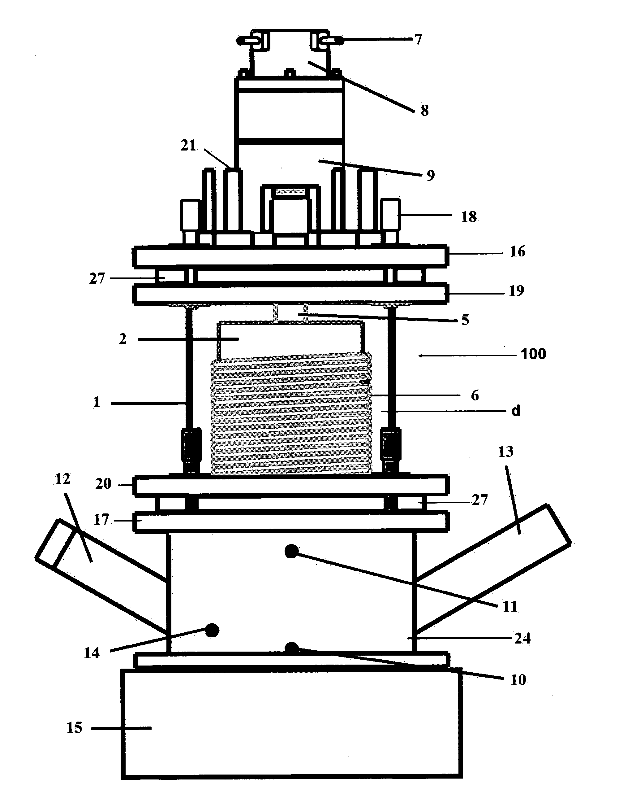
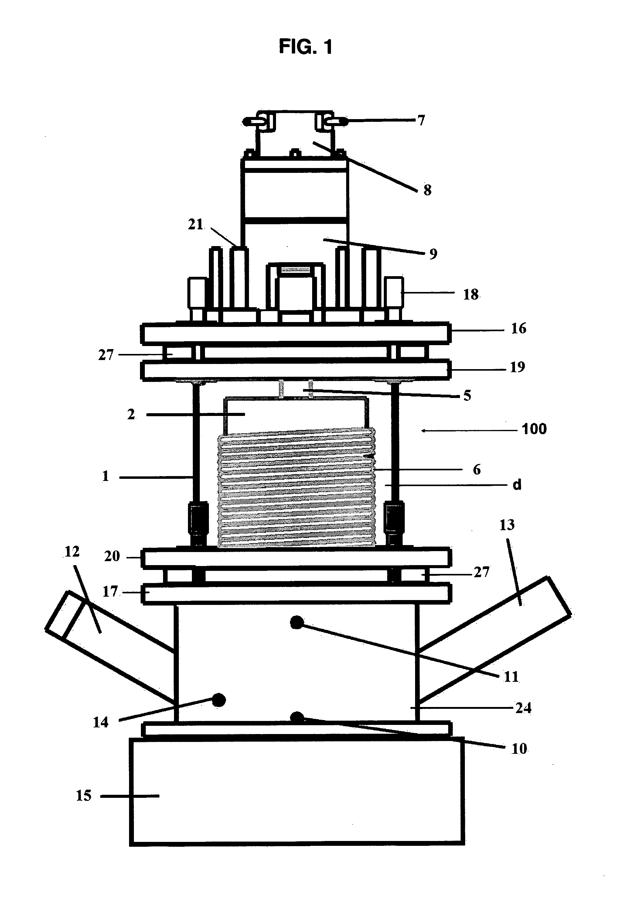
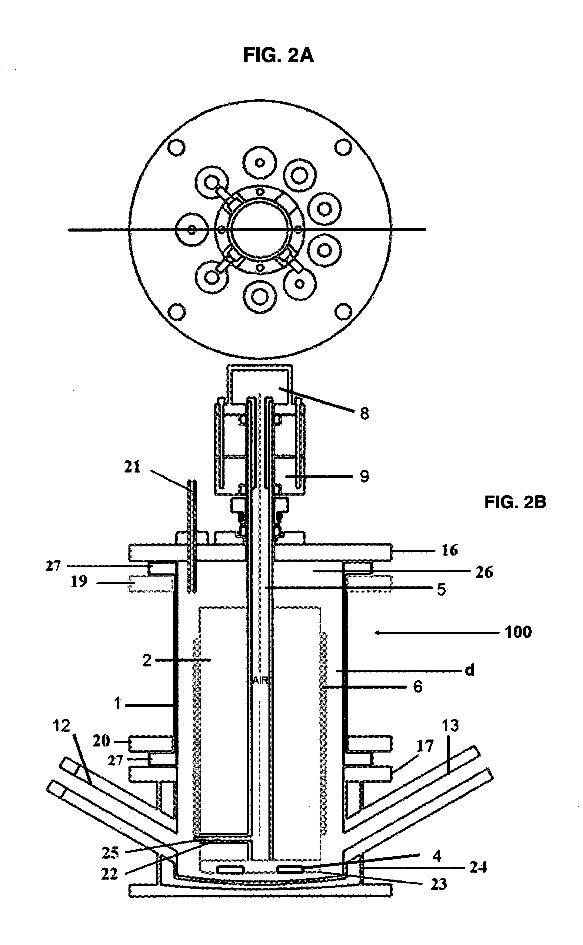
[0032]c) a dense polymeric tubular membrane highly permeable to gases such as the ones made of silicone, wherein said membrane is wrapped around the whole said internal body, which enables an efficient transfer by diffusion of the gases present in the interior of the membrane to the culture media;
[0043]The invention also provides a bioreactor of Taylor vortexes flow comprising efficient devices for heat and mass transfer, presenting low shear stress.
[0045]The invention also provides a bioreactor of Taylor vortexes flow of easy scaling up of the aeration system through the use of longer tubular membranes.

Problems solved by technology

Another result observed was that the rotation of solely the external cylinder, while the internal remains stationary, does not enable the formation of vortexes.
These equipments do not present geometric characteristics and do not operate with the intention of forming the Taylor-Couette flow.
In these works, although innovations regarding the use of bioreactor for the cultivation of animal and plant cells are proposed, serious obstacles hinder the scaling up process.
These oxygenation systems cause the restriction in the volumetric capacity (100 mL) of the equipment, once these techniques are not appropriated for the cultivations with high cellular density (>106 cells·mL−1).
The limitation to the heat transport is due to the absence of heat exchange in the bioreactors structure.
With that, there is a limitation in the relation of oxygen exchange area by reactor volume.
This characteristic made them inappropriate for cell culture due to the shear stress generated by the agitation and aeration systems as well as the cell damage caused by the systems, according to Cartwright, T.

Method used


Image

  • Taylor Vortex Flow Bioreactor for Cell Culture
  • Taylor Vortex Flow Bioreactor for Cell Culture
  • Taylor Vortex Flow Bioreactor for Cell Culture

Examples


Embodiment Construction

[0055]The Taylor vortexes flow is appropriate principally for the culture involving shear-sensitive cells, such as animal and plant cells, once the transition from the Couette flow to Taylor flow generates as global effect the reduction of shear. This reduction of the shear stress (tangential) is due to the decomposition, by the vortex, of the tension applied by the internal cylinder in the three components: axial, radial and tangential.

[0056]This condition provide a well defined flow pattern with appropriate mixing of the culture media, ensuring favorable conditions of pH, dissolved oxygen, temperature and nutrients to the cells. This is a different fact from those observed with other employed systems for cell culture, such as Spinner-type flask, roller bottles and conventional bioreactors, such as the agitating tank type.

[0057]The models of Taylor vortexes flow are based on the Taylor number (Ta) or rotational Reynolds number (Reθ). Both numbers are non-dimensional and reflect the...


PUM

PropertyMeasurementUnit
aspect ratioaaaaaaaaaa

Abstract

The invention concerns a rotating wall vessel bioreactor (100) using Taylor vortex flow for cell culture in the annular space between the two concentric cylindrical bodies, wherein the internal one (2) is rotating and the external one (1) is stationary. The internal rotating body (2) is composed of an external wall around which a polymeric tubular membrane (6) is wrapped, which is connected to the hollow tubular axis (5) of the internal body (2) for the introduction of gases into the annular space (d). Said annular space (d) is filled with a suspension of cells or cells immobilized on microcarriers.

Description

FIELD OF THE INVENTION[0001]The present invention relates to the field of bioreactors used for the culture of animal and plant cells, more specifically, to a bioreactor based on Taylor vortexes flow.BACKGROUND OF THE INVENTION[0002]The containment of a fluid between two concentric cylinders, which the internal (and maybe the external) cylinder is rotating, is a classical theme in fluid dynamics and it was described for the first time by Taylor in the work Taylor, G. I. “Stability of a viscous liquid between rotating cylinders”. Philosophical Transactions of Royal Society A, v. 223, p. 289-343, 1923.[0003]In his studies, the researcher examined the beginning of the formation of a secondary flow in the annular space between two concentric cylinders under rotation simultaneous or in separate. Taylor proved experimentally that in internal cylinder rotation speeds below of a determined value, the fluid simply moved tangentially in the annular space. However, in the moment the rotation sp...

Claims


Application Information

Patent Timeline
Patent Type & Authority Applications(United States)
IPC IPC(8): C12M1/10C12M3/00
CPCC12M23/24C12M23/38C12M27/04C12M41/32C12M41/18C12M41/26C12M29/04
Inventor SUAZO, CLAUDIO ALBERTO TORRESGIORDANO, ROBERTO DE CAMPOSSANTIAGO, PATRICIA APARECIDA
Owner UNIVE FEDERAL DE SAO CARLOS
Learn More