

Cyclical epitaxial deposition and etch
- Summary
- Abstract
- Description
- Claims
- Application Information
AI Technical Summary
Benefits of technology
Problems solved by technology
Method used
Image

Examples
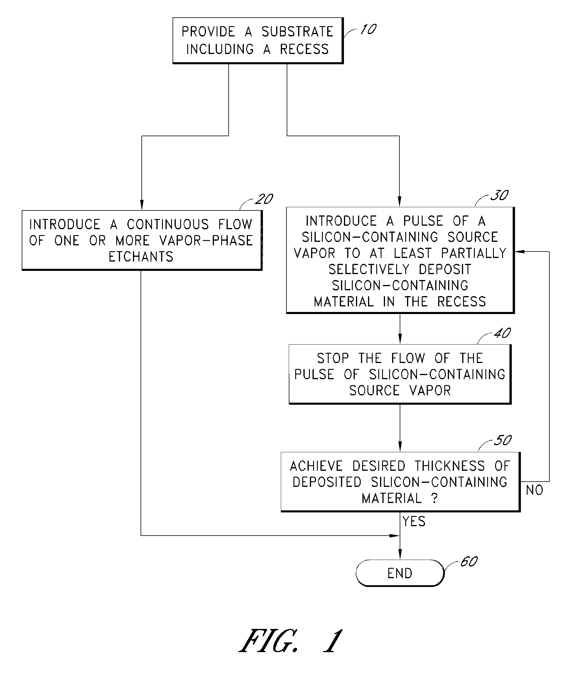
example process
PARAMETERS
Example 1
[0071]Example process parameters are summarized in Table A below, which lists operating ranges for a selective deposition process according to one embodiment using either Cl2 or HCl as an etchant gas. Optional ranges are provided in parentheses. As is evident from Table A, the process conditions such as chamber temperature, chamber pressure and carrier gas flow rates, are preferably substantially similar throughout the selective deposition process, thereby allowing throughput to be increased. Thus, the example below employs isothermal and isobaric conditions during the selective formation process.
TABLE AProcess PhasePre-SelectiveTransition Period toPost-EtchDepositionEpitaxialSelective EpitaxialPurge(one time atGrowthEtchGrowth (SEG);(one time atbeginning)(SEG)Backrepeat x-timesend)duration (sec)52.4-12 2.4-30 .1 s10temp (° C.)525-600 525-600 525-600 525-600 525-600 pressure (Torr)10-20010-20010-20010-20010-200H2 / He flow (slm)2-202-202-202-202-20Cl2 / HCl flow (sccm...
example 2
[0077]Example process parameters are summarized in Table B below, which lists operating ranges for a selective deposition process according to one embodiment using HCl as an etchant gas. Optional ranges are provided in parentheses. As is evident from Table B, the process conditions such as chamber temperature and chamber pressure, are preferably substantially similar throughout the selective deposition process, thereby allowing throughput to be increased. Thus, the example below employs isothermal and isobaric conditions during the selective formation process.
TABLE BTransitionPre-Period toDepositionDeposition(once at(repeat 30beginning)DepositionPurge 1Purge 2EtchPurge 3Purge 4times)Time303.63.62.463.62.40.1[s]PurposeSiCP(Ge)Purge outRamp downEtch Ge withRamp updepSi3H8, MMS,Hehigh HCL / lowHePH3HeTokenDepDepDepDepDepDepDepDepTemp525525525525525525525525[° C.]Pressure200200200200200200200200[Torr]He [slm]1010102221010Si3H8100V100———100V100V100V[mg / min]MMS60V6060V60V60V60V6060[sccm]PH3...
PUM
 Abstract
Description
Claims
Application Information