
Shiftable clutch device, particularly friction wet clutch, drive train for a hybrid system and method for operating the drive train and vehicle including the drive train

a technology of shifting clutch and wet clutch, which is applied in the direction of electric energy vehicles, fluid gearings, gearing control, etc., can solve the problems of safety risk, affecting the operation of hydraulic systems, and unable to idle, so as to build up the required pressure relatively quickly and increase the flexibility of assembly

Active Publication Date: 2011-05-19
SCHAEFFLER TECH AG & CO KG
View PDF4 Cites 32 Cited by
  • Summary
  • Abstract
  • Description
  • Claims
  • Application Information

AI Technical Summary

Benefits of technology

However, it is a substantial disadvantage of a system of this type that the known hydraulic systems employed, in particular during a standstill of one or both drive machines, e.g. also during a short time standstill, can idle due to the lacking driving of the transmission oil pump, since the loop is not maintained through the transmission oil pump due to the lack of propulsion, and the operating medium disposed in the system is run back to the operating medium supply through the respective return. When starting up again, e.g. when actuating the gas pedal, initially the hydraulic supply and thus the transmission oil pump would have to be driven, which in turn has to supply sufficient pressure and volume, so that the required shifting devices that have to be actuated are loaded and the hydrodynamic component is filled. Since this leads to substantial delays in the reaction to the actuation of the gas pedal, which may also create a safety risk in many situations, there is the necessity that the hydraulic system of the transmission has to be kept loaded with a low pressure also when the vehicle is standing still. The transmission oil pump used, thus has to be able to cover in particular the leakages of the hydraulic system when standing still. In order to assure this, the prior art often uses an additional electrically driven oil pump. Alternatively, the electrical machine of the hybrid system and the existing main oil pump can be used, which however, has technical disadvantages. Thus, an additionally provided and electrically driven oil pump creates substantial additional complexity. On the other hand, also, not using an additional pump of this type is associated with numerous disadvantages. When the clutch device is open in a state without pressure for an embodiment of this type, emergency operating capabilities are not assured anymore. Even when the combustion engine is started through an additional starter, no oil pressure can be built up in the transmission, since the clutch device “open without pressure” cannot be closed, so that the oil pump is being driven. However, when a clutch device is being used which is closed in a condition without pressure, the transmission oil pump is immediately also driven in emergency operating mode and the system operates like the system of a conventional automatic transmission. However, the high complexity for adapting the clutch device is a substantial disadvantage.
In a particularly preferable manner the transmission and / or the force transmission device and / or the actuatable clutch device is associated with a operating medium supply and / or routing system including at least one feed drive, in particular a transmission oil pump which is mechanically coupled with the input of the force transmission device. The transmission oil pump is also driven through transmitting a torque to the input of the force transmission device and can build up a required pressure without an additional pump relatively quickly also when the shiftable clutch device is disconnected.

Problems solved by technology

However, it is a substantial disadvantage of a system of this type that the known hydraulic systems employed, in particular during a standstill of one or both drive machines, e.g. also during a short time standstill, can idle due to the lacking driving of the transmission oil pump, since the loop is not maintained through the transmission oil pump due to the lack of propulsion, and the operating medium disposed in the system is run back to the operating medium supply through the respective return.
Since this leads to substantial delays in the reaction to the actuation of the gas pedal, which may also create a safety risk in many situations, there is the necessity that the hydraulic system of the transmission has to be kept loaded with a low pressure also when the vehicle is standing still.
Alternatively, the electrical machine of the hybrid system and the existing main oil pump can be used, which however, has technical disadvantages.
Thus, an additionally provided and electrically driven oil pump creates substantial additional complexity.
When the clutch device is open in a state without pressure for an embodiment of this type, emergency operating capabilities are not assured anymore.
Even when the combustion engine is started through an additional starter, no oil pressure can be built up in the transmission, since the clutch device “open without pressure” cannot be closed, so that the oil pump is being driven.
However, the high complexity for adapting the clutch device is a substantial disadvantage.
For the known drive trains, however, problems can occur when controlling the engine clutch when the transmission is e.g. malfunctioning due to a control error and is being operated in an emergency mode.
When an error of this type occurs also a possibly existing additional pump is not usable since it is also controlled by the transmission control.

Method used


Image

  • Shiftable clutch device, particularly friction wet clutch, drive train for a hybrid system and method for operating the drive train and vehicle including the drive train
  • Shiftable clutch device, particularly friction wet clutch, drive train for a hybrid system and method for operating the drive train and vehicle including the drive train
  • Shiftable clutch device, particularly friction wet clutch, drive train for a hybrid system and method for operating the drive train and vehicle including the drive train

Examples


Embodiment Construction

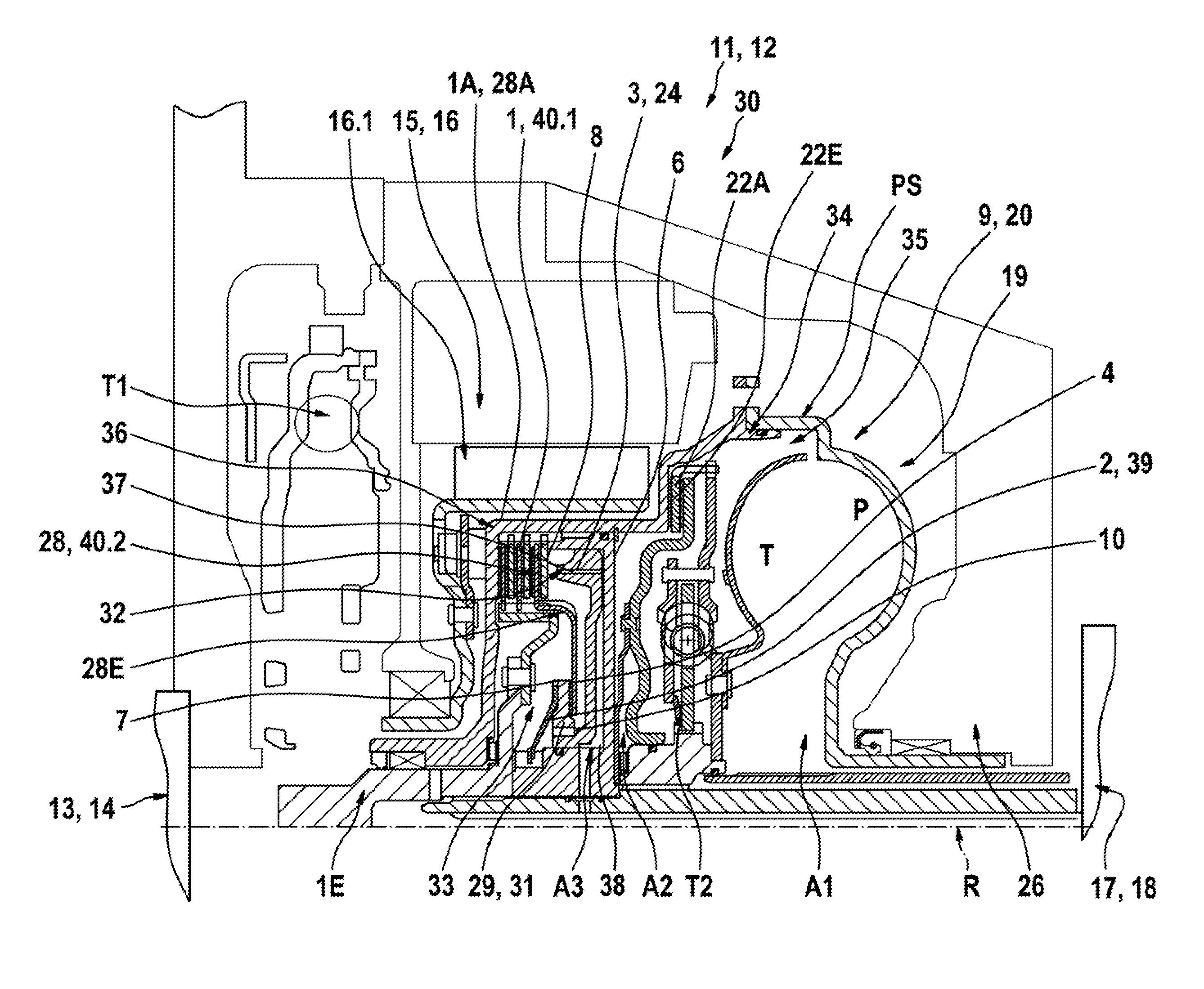
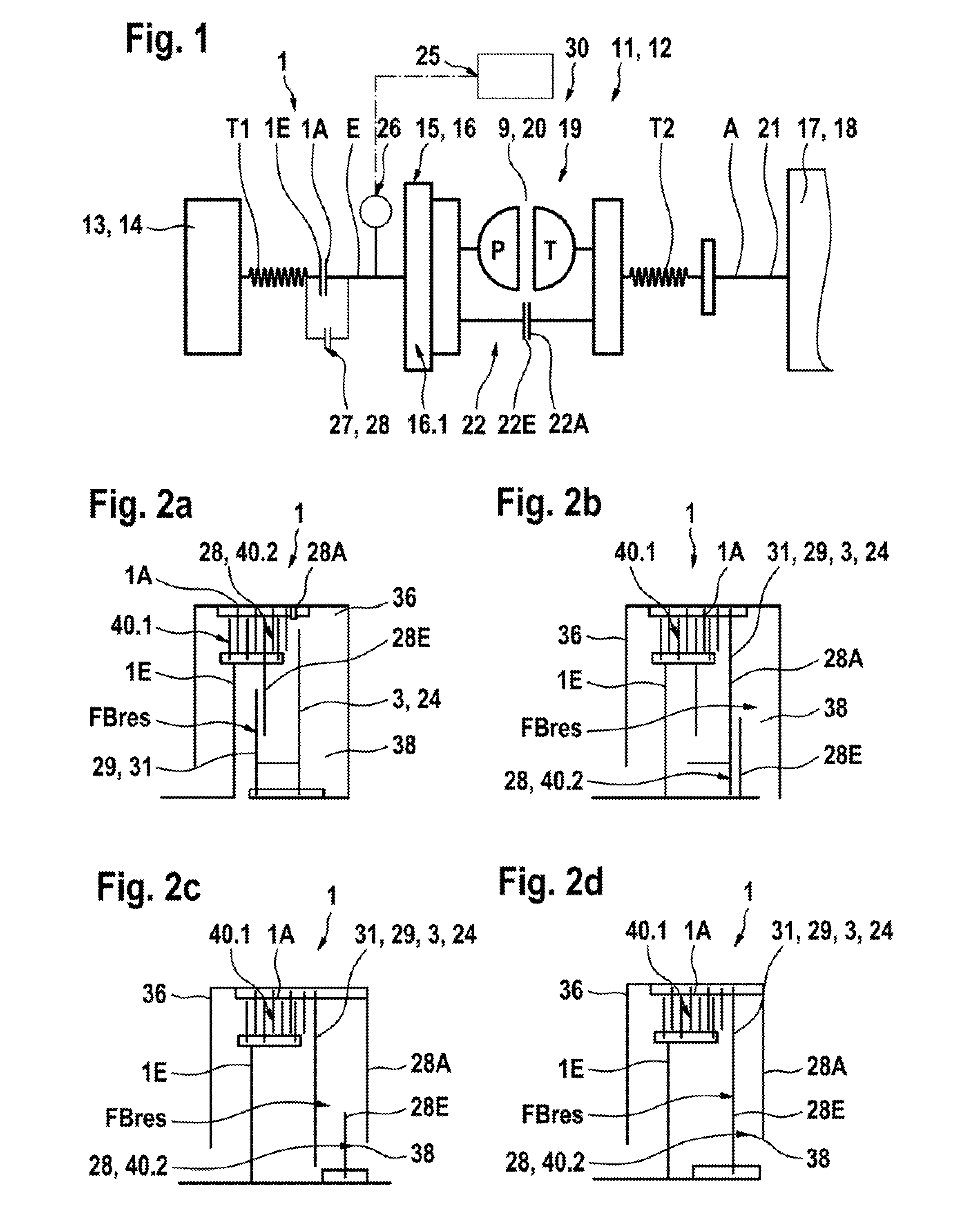
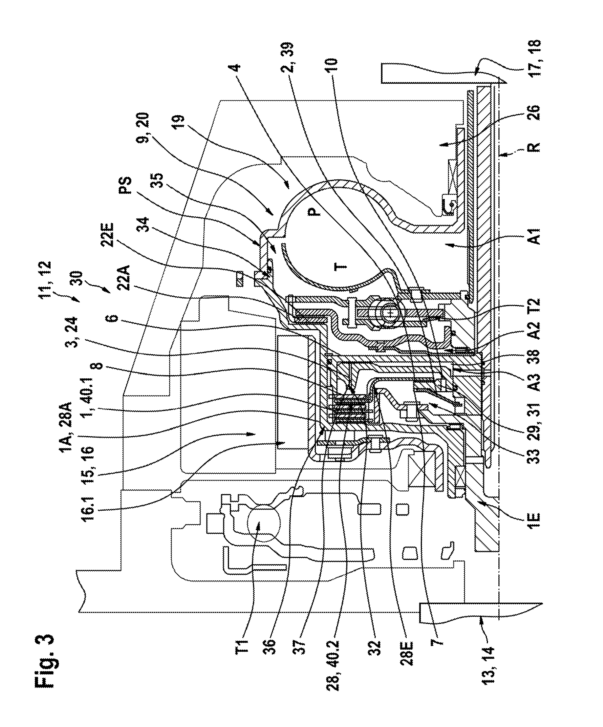
FIG. 1 illustrates the basic configuration and the basic function of a drive train 11 configured according to the invention in a simplified schematic depiction for a hybrid system 12 for use in vehicles. The drive train includes a first drive machine 13 which includes at least a firsts drive machine 13 which is configured in the form of a internal combustion engine 14, in particular a diesel engine and the drive train includes a second drive engine 15 which is configured as an electrical machine 16 which is operable at least as a motor and / or as a generator. The coupling of the particular drive machines 13 and 15 with additional transmission units 17 in the drive train 11 in particular configured as a transmission 18 and the remaining components of the drive train 11 coupled with the transmission is performed through a force transmission device 19 including an input E configured to be coupled with the respective drive machine 13, 15, at least one output A connected with the transmis...


PUM


Abstract

A shiftable clutch device for disconnecting a first drive machine from a drive train and connecting it thereto, including a control device that can be actuated by a pressure medium, is characterized according to the invention in that the shiftable clutch device includes two partial clutches, a first partial clutch forming a main clutch and a second partial clutch forming a drag clutch, which are disposed and configured such that each is adapted to produce a drag torque in an end position of the control device, a first opening end position characterized by an open state of the main clutch and a second closing end position characterized by a closed state of the main clutch.

Description

FIELD OF THE INVENTIONThe invention relates to a shiftable clutch device, in particular a friction wet clutch, for disconnecting and connecting a first drive machine from a drive train, the clutch device including a control device that can be actuated by a pressure medium.The invention also relates to a drive train for a hybrid system for a vehicle, including at least a first drive machine and a second drive machine, which are connectable with a transmission or another transmission unit separately or jointly through a force transmission device, and including a shiftable clutch device for disconnecting and connecting the first drive machine from the drive train, wherein the clutch device is disposed between the first drive machine and the force transmission device.The invention furthermore relates to a method for operating a drive system of this type.BACKGROUND OF THE INVENTIONHybrid systems for vehicle applications are known in the art in a plurality of embodiments. They all have in...

Claims


Application Information

Patent Timeline
Patent Type & Authority Applications(United States)
IPC IPC(8): B60W10/02F16D47/00F16H45/02B60W20/00
CPCB60K6/387B60K6/48F16D25/0638F16D25/10Y10T477/78F16H2045/002Y02T10/6221Y10T477/26F16H61/62F16D21/06Y02T10/62
Inventor MUELLER, BRUNOMOVLAZADA, PARVIZKRAUSE, THORSTEN
Owner SCHAEFFLER TECH AG & CO KG
Learn More