Galvanic skin treatment device
a skin treatment and galvanic technology, applied in the field of galvanic skin treatment devices, can solve problems such as inability to use conventional electrical devices
- Summary
- Abstract
- Description
- Claims
- Application Information
AI Technical Summary
Benefits of technology
Problems solved by technology
Method used
Image
Examples
example 1
[0167]A galvanic couple according to the invention was prepared as follows. A first conductive electrode comprising zinc and a second conductive electrode comprising silver / sliver chloride were screen printed onto a substrate comprising Mylar film. An ink formulation comprising pharmaceutically acceptable binder, plasticizer, solvent and metallic zinc was used as the material for the first conductive electrode. An ink formulation comprising pharmaceutically acceptable binder, plasticizer, solvent and silver chloride was used as the material for the second conductive electrode. Metallic silver powder was added to both inks to increase electrical conductivity of the printed traces.
[0168]The printed zinc trace was 1 mm wide by 10 mm long and was printed through a 195 mesh polyester screen. The silver / silver chloride trace was 2 mm wide by 10 mm long and was printed through a 255 mesh polyester screen. The electrodes were oriented such that the 10 mm axes were parallel to each other and...
example 2
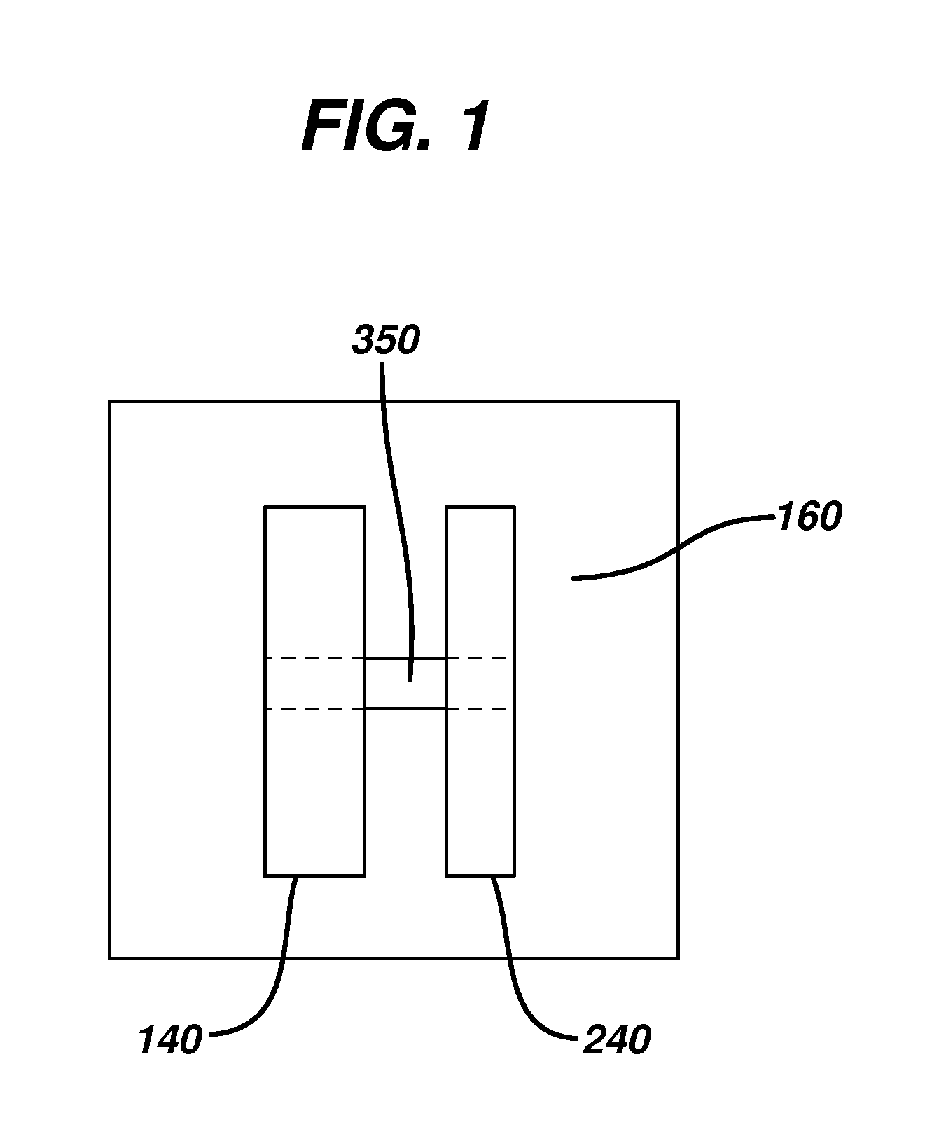
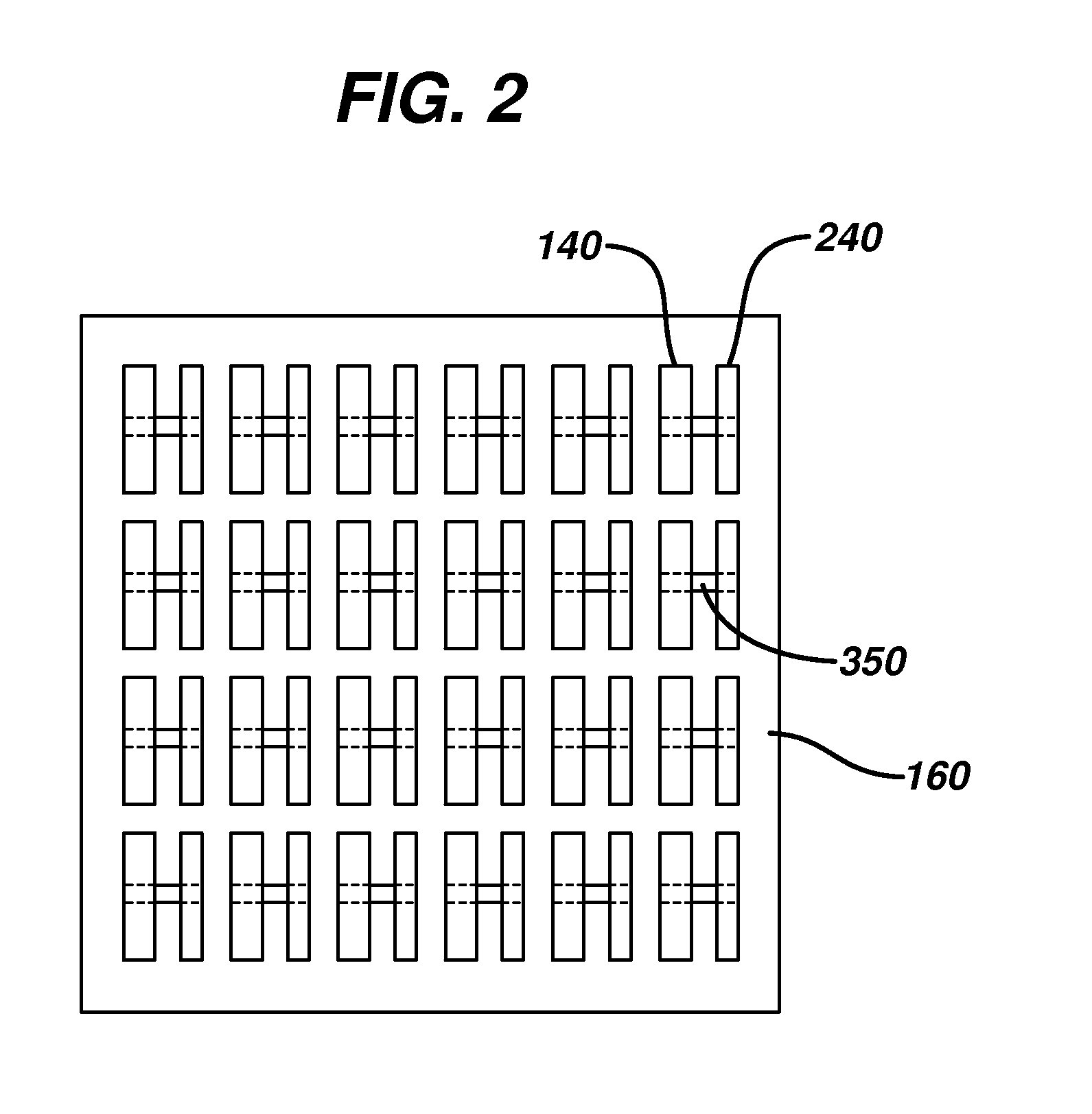
[0175]In this example a plurality of discrete galvanic couple composed of zinc (anode) and silver / silver chloride (cathode) inks were screen printed onto Mylar film as described in Example 1. However, these electrodes were brought into contact and electrical communication by a protrusion of the zinc trace, also composed of zinc ink, which was connected to the silver / silver chloride trace. This protrusion, the zinc bridge, was 0.25 mm in width and 5 mm in length, and yielded a resistance of about 20 ohms across the galvanic couple. The overall design consisted of an ‘H’ pattern with zinc and silver / silver chloride representing the vertical legs of the ‘H’ and zinc representing the connecting bar as shown in FIG. 3. In essence the zinc was a “T” shape that was rotated by 90 degrees. The galvanic couple was printed in two steps as opposed to the three step galvanic couple described in Example 1. The zinc ‘T’ was printed prior to the silver / silver chloride trace.
[0176]An array of these ...
example 3
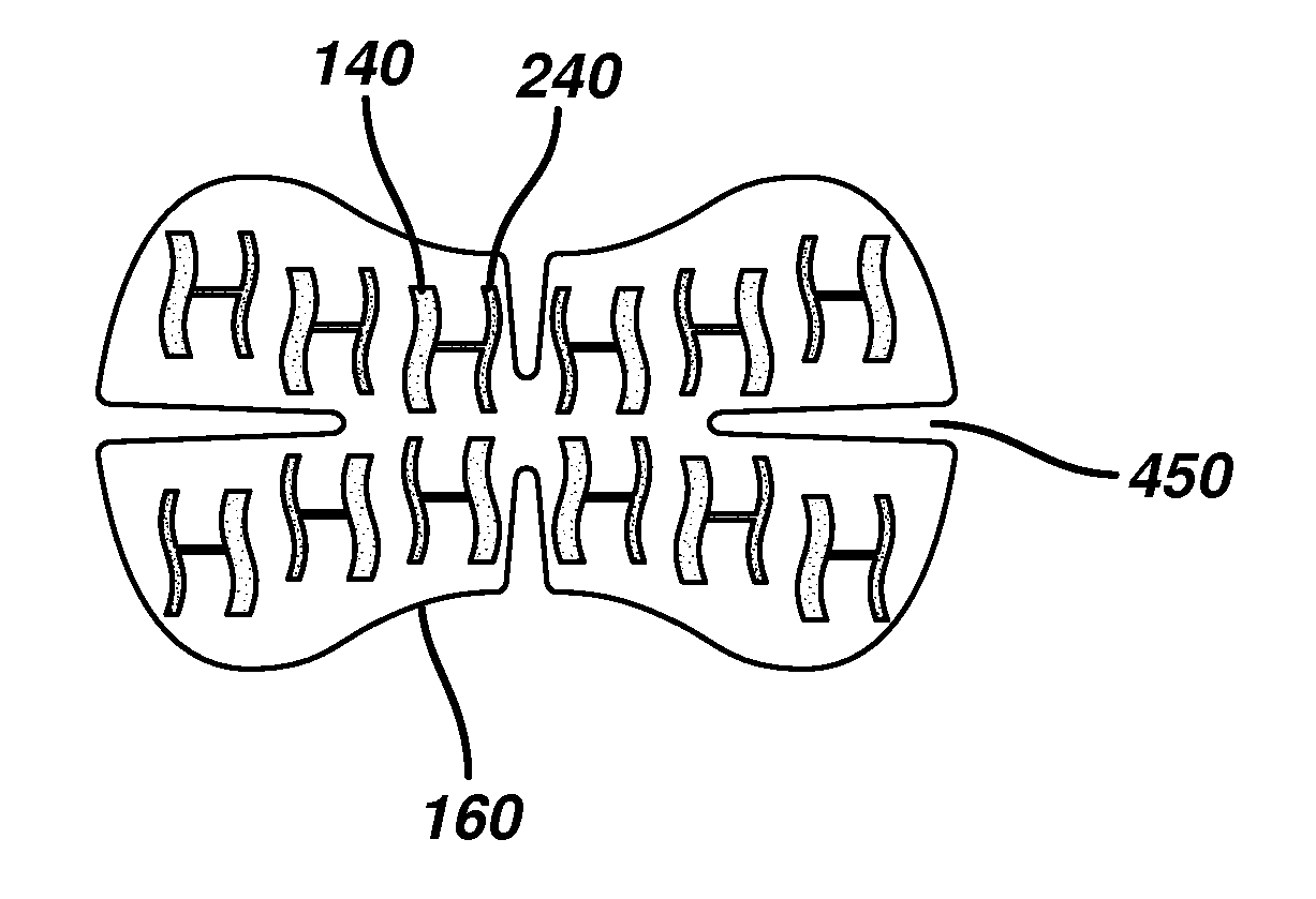
[0178]A device according to the invention was made comprising zinc and silver / silver chloride wavy electrodes. This was done to enhance the aesthetics of the galvanic couples within the array. Although the electrodes were wavy, the spacing between the zinc and silver / silver chloride traces was fixed at all points along the long axis of each galvanic couple to ensure evenly distributed electrical current between electrodes. Electrical performance and delivery of compounds into the skin were similar to that of Example 2.
PUM
 Abstract
Description
Claims
Application Information
 - R&D
- Intellectual Property
- Life Sciences
- Materials
- Tech Scout
- Unparalleled Data Quality
- Higher Quality Content
- 60% Fewer Hallucinations
Browse by: Latest US Patents, China's latest patents, Technical Efficacy Thesaurus, Application Domain, Technology Topic, Popular Technical Reports.
© 2025 PatSnap. All rights reserved.Legal|Privacy policy|Modern Slavery Act Transparency Statement|Sitemap|About US| Contact US: help@patsnap.com


