

Random number generating method and random number generating apparatus
a random number and generating method technology, applied in the direction of pulse generation with predetermined statistical distribution, instruments, computing, etc., can solve the problems of image quality disturbance, difficult to generate random numbers of a plurality of lengths from a single random number generator, and inability to generate an identical random number sequence in the reverse direction
- Summary
- Abstract
- Description
- Claims
- Application Information
AI Technical Summary
Benefits of technology
Problems solved by technology
Method used
Image

Examples
first embodiment
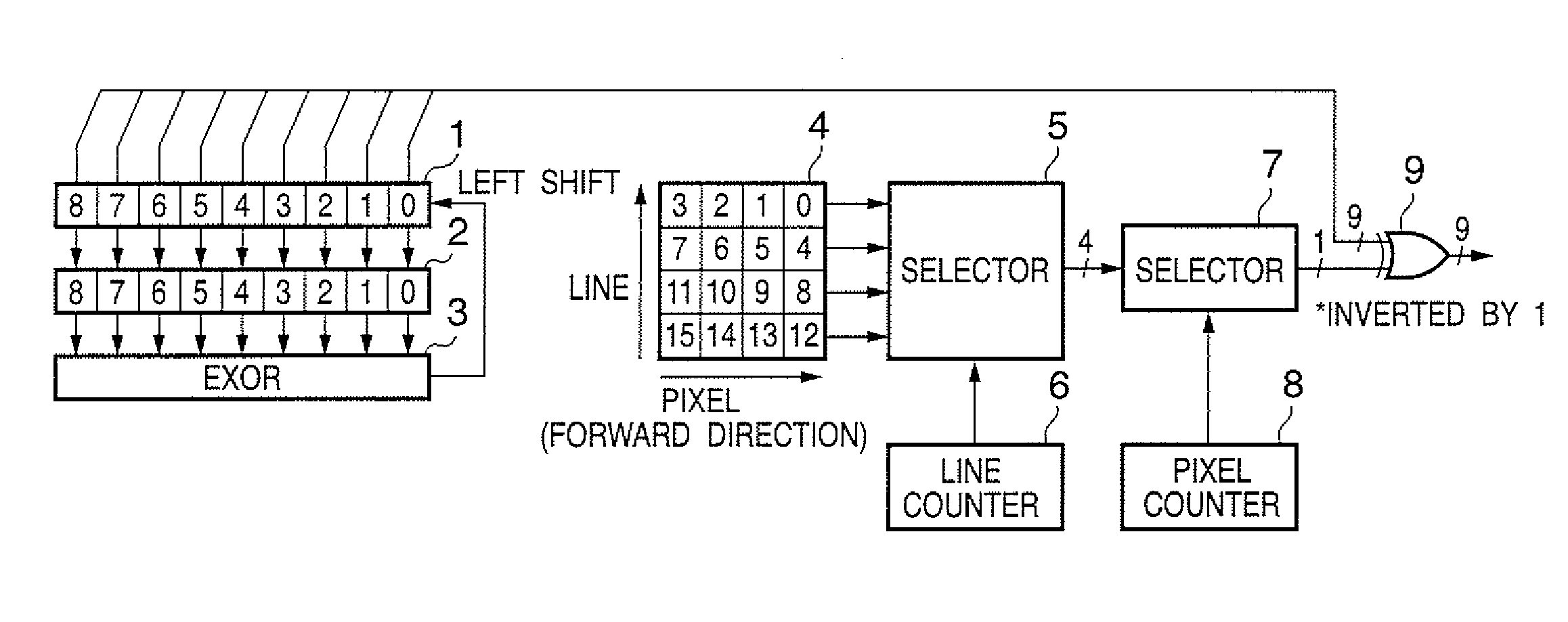
[0077]FIG. 1 is a block diagram showing the basic arrangement of a random number generator according to this embodiment. This embodiment will exemplify a case wherein random numbers for all pixels that form an image are to be generated.
[0078]Referring to FIG. 1, reference numeral 1 denotes a shift register which can shift a bit sequence to be held in both the right and left directions; 2, a mask circuit which masks the bit sequence output from the shift register 1; 3, an EXOR circuit; 4, a pattern table; 5, a line direction selector; 6, a line counter; 7, a pixel direction selector; 8, a pixel counter; and 9, an inverter. In the following description, the number of bits of the shift register 1 is K (K=9 in FIG. 1), i.e., the random number generator that ranges a random number expressed by 9 bits will be explained. However, the gist of the following description is not limited to 9 bits.
[0079]The shift register 1 shifts the held bit sequence 1 bit to the left every time it generates a...
second embodiment
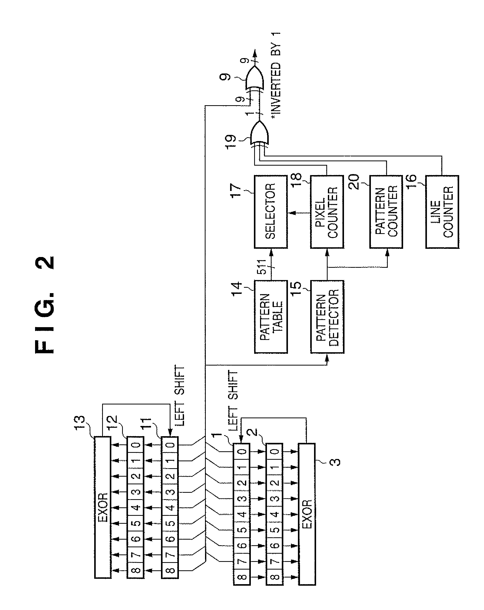
[0090]FIG. 2 is a block diagram showing the basic arrangement of a random number generator according to this embodiment. Note that the same reference numerals in FIG. 2 denote the same parts as in FIG. 1, and a description thereof will be omitted. Referring to FIG. 2, reference numeral 11 denotes a shift register; 12, a mask circuit; 13, an EXOR circuit; 14, a pattern table; 15, a pattern detector; 16, a line counter; 17, a selector; 18, a pixel counter; 19, an EXOR circuit; and 20, a pattern counter.
[0091]The shift register 11, mask circuit 12, and EXOR circuit 13 are respectively the same as the shift register 1, mask circuit 2, and EXOR circuit 3, and operate, as described in the first embodiment. By setting a mask of the mask circuit 12 to be different from that of the mask circuit 2, a random number having a different sequence (primitive polynomial) from that generated by the shift register 1, mask circuit 2, and EXOR circuit 3 is generated. By loading the value of the shift re...
third embodiment
[0103]FIG. 3 is a block diagram showing the basic arrangement of a random number generator according to this embodiment. Note that the same reference numerals in FIG. 3 denote the same parts as in FIGS. 1 and 2, and a description thereof will be omitted. Referring to FIG. 3, reference numerals 21 and 22 denote EXOR circuits; 23, 24, and 25, selectors; 26, a pattern detector; 27, a pixel counter; and 28, an EXOR circuit.
[0104]The selector 23 receives 9 bits from the shift register 11, selects a predetermined number of bits equal to or smaller than 9 bits (4 bits in FIG. 3), and inputs them to the EXOR circuit 21. If the number of “1”s of the input bit sequence of 4 bits is an even number, the EXOR circuit 21 outputs 0; if it is an odd number, the EXOR circuit 21 outputs 1. The EXOR circuit 21 inputs the output value to the shift register 11. Since the maximum value of the number of terms except for a “+1” term of primitive polynomials of 9-th order or less is 4, the EXOR circuit 21 s...
PUM
 Abstract
Description
Claims
Application Information