CO Generator and Process for Desulfurizing Solid Carbon-based Fuels

Inactive Publication Date: 2011-05-26
HERRINGTON LOUIS
View PDF7 Cites 7 Cited by
  • Summary
  • Abstract
  • Description
  • Claims
  • Application Information

AI Technical Summary

Benefits of technology

[0023]It is still a further objective of this invention to improve efficiency of the external hot CO generator by redirecting a portion of the generated hot gas through the solid fuel feeding the Combustor for purposes of desulfurizing and/or preheating the solid fuel. Highly pure CO can be generated in the Combustor using only O2 and CO2 when sulfur and certain other impurities have been removed prior to burning the solid carbon fuel. Alternately, simply partial preheating of the supply column can assure that the hot zone remains at the top of the Combustor while allowing a larger portion of the generated gas to go directly to the users of the hot gas stream.
[0024]Although the Combustor described in this embodiment is described in combination with a closed-loop system for desulfurizing petroleum coke, it is to be understood that the Combustor can act as a generator of CO for other processes for which CO is a required feed stream. The Combustor is also capable of producing CO in varying concentrations by adjustment of inert gas flows there into. When ambient air is used as a reactant in the Combustor, both the cost of hot CO generated and the concentration are reduced. By addition of dry ambient air

Problems solved by technology

Desulfurization methods that contact coke with an inert gas are generally categorized with the temperature/time processes and have limited sulfur removal efficiency.
One drawback of thermal-time processes is that high sulfur removal requires high temperatures, which often results in loss of coke yield and product density.
One problem with this patent is that the in

Method used


Image

  • CO Generator and Process for Desulfurizing Solid Carbon-based Fuels
  • CO Generator and Process for Desulfurizing Solid Carbon-based Fuels
  • CO Generator and Process for Desulfurizing Solid Carbon-based Fuels

Examples


Example

DETAILED DESCRIPTION OF THE FIGURES

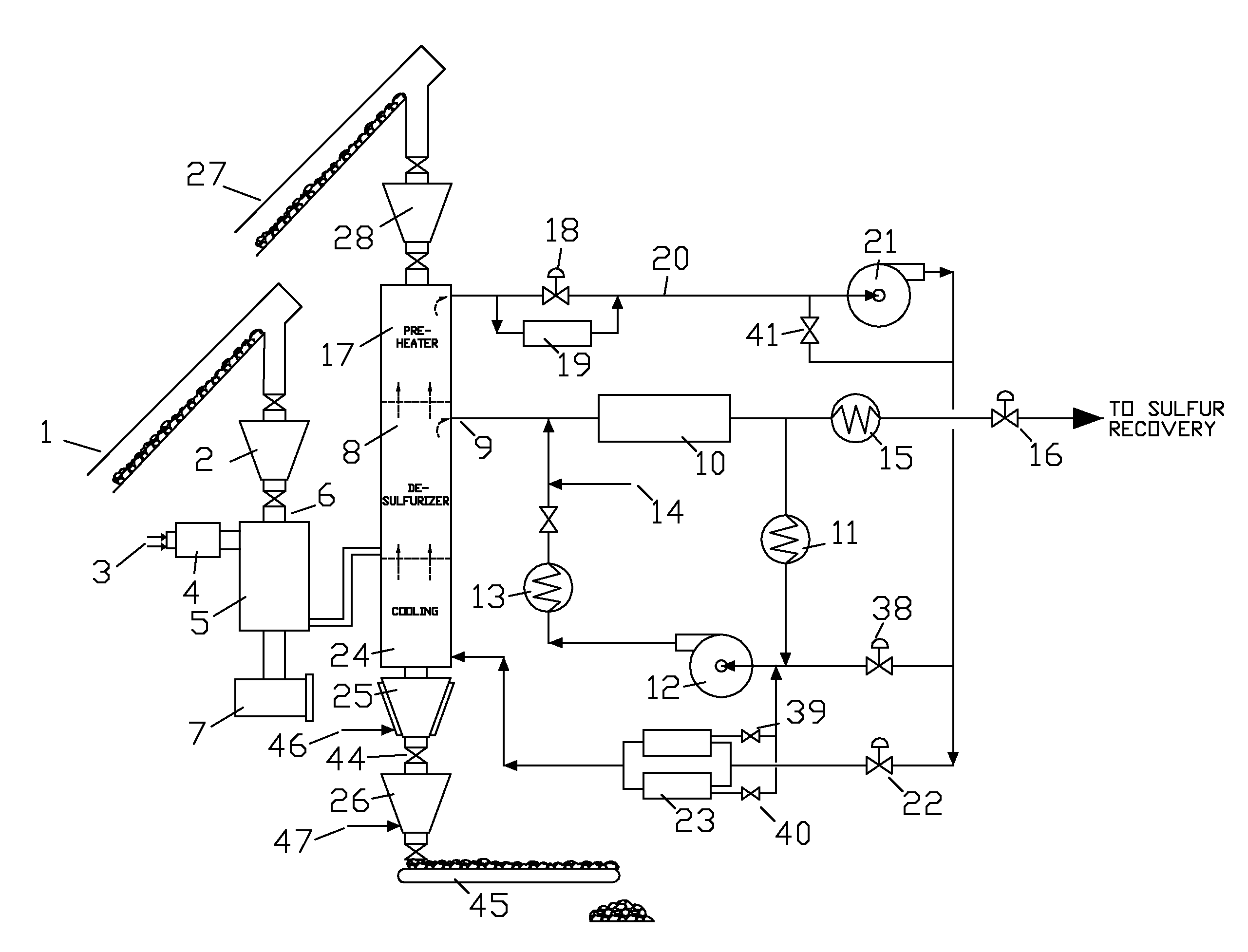
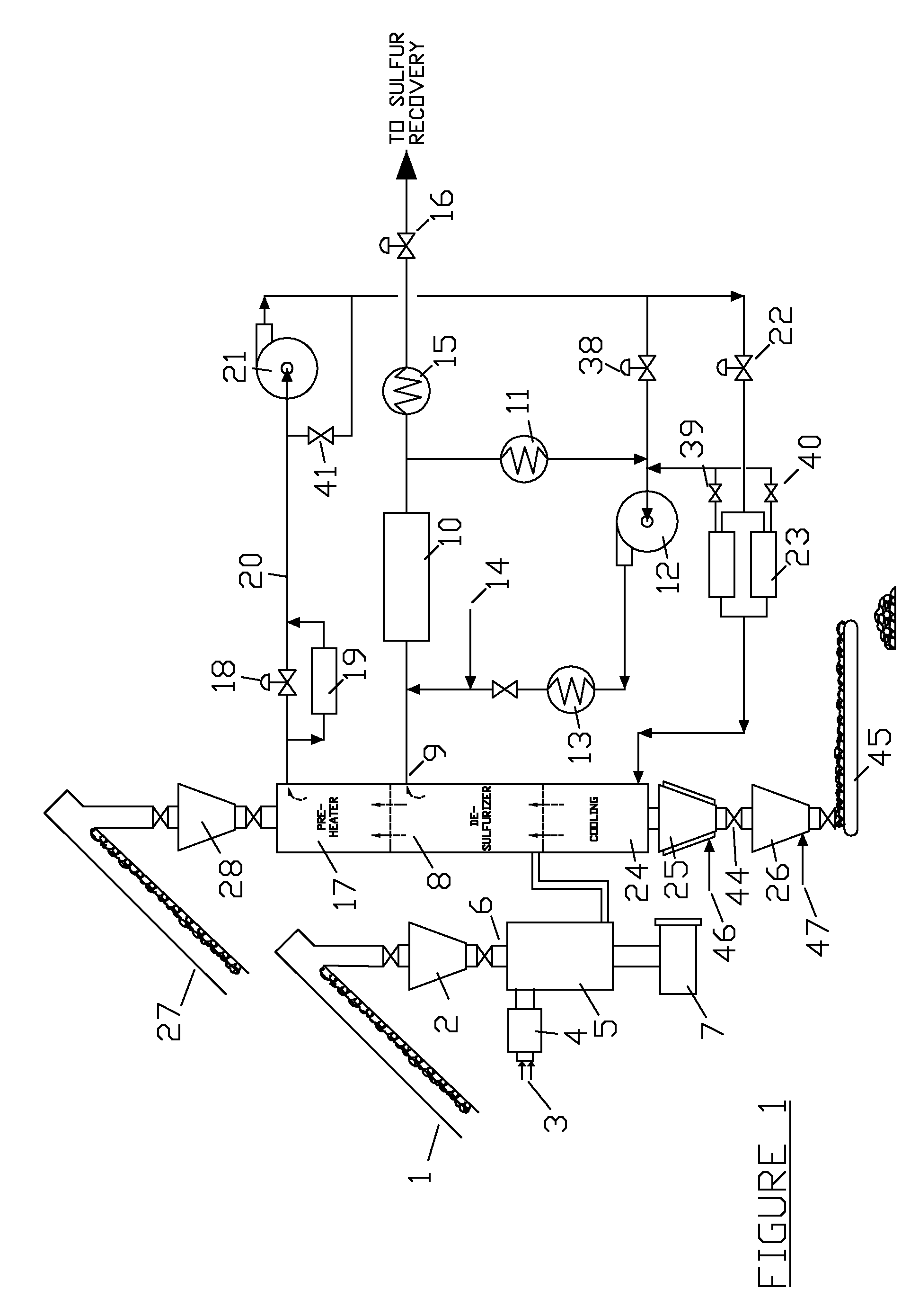
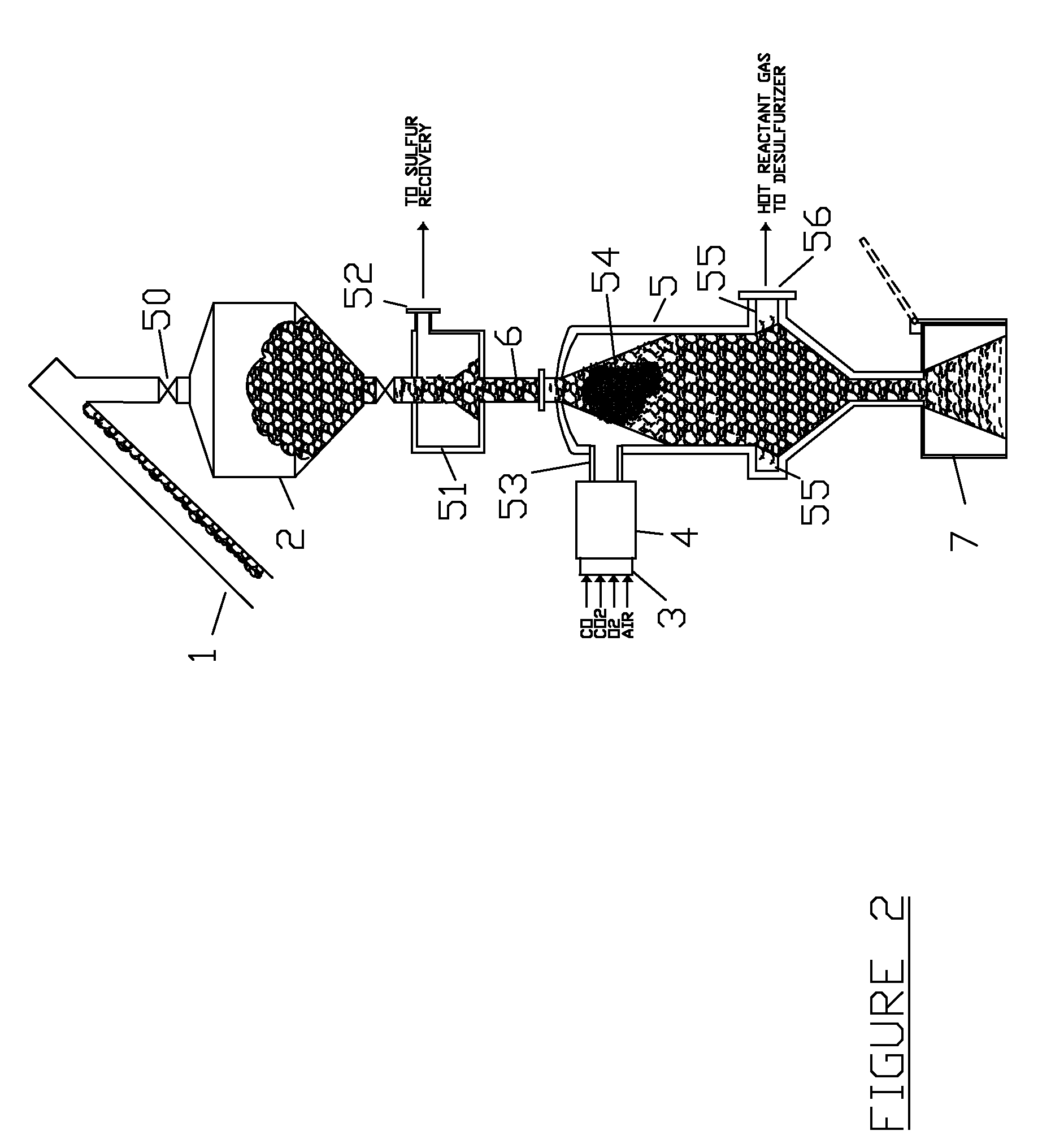
[0029]FIG. 1 shows a process schematic of the present invention. An elevator 1 containing a low-value, calcined fuel coke brings fuel to a hopper 2. Coke from the hopper 2 is supplied to the combustor 5 through a supply column 6. The fuel coke fills the Combustor 5 and debris bin at 7. A start-up burner 3 operates with CO gas and Oxygen. The mixed and ignited gases flow into oxidizer at 4. Hot gas from the Oxidizer passes into the combustor where the fuel coke is heated and ignited. All oxygen in the gases is consumed in the Combustor. Part of the hot combustor gas flows back up the supply column 6 at a controlled rate and is vented to a collection header that feeds a standard sulfur recovery process. The hot gases vented back to the supply column 6 pre-heat coke fuel entering the combustor to replace burned coke. Preheating the fuel coke assures that the combustion zone remains at the top of the Combustor 5. As coke flows into the Combustor, the c...


PUM


Abstract

A process is presented whereby hot Carbon Monoxide (CO) gas is generated under pressure in an external Combustor by the partial oxidation of a carbon-based solid fuel. This pressurized, hot CO gas or CO gas mixture is then transferred to a desulfurizing vessel containing a second carbon-based solid fuel. The hot CO laden gas and solid material contact in a counter-flow arrangement where the CO reacts with and removes sulfur impurities from the second carbon fuel. The temperature of the pressurized CO laden gas from the Combustor is controlled by varying the oxidizer feed gas composition. The Combustor also contains a means for desulfurizing its feed fuel by flowing a portion of the hot CO gas generated up through the inlet solid fuel feed line. The desulfurizer vessel is comprised of three stages, a preheat stage, a desulfurizing stage, and a cooling stage. Hot CO gas from the Combustor enters the desulfurizer section where it mixes with a recycle gas stream coming up from the cooling stage below. The gas exiting the desulfurizer section is split into an exhaust stream and a recycle stream. The recycle stream travels up through the preheat section and heats the incoming material being treated. The cooled recycle gas exits the top of the system and flows to a recycle blower. The recycle gas is scrubbed of impurities by activated carbon prior to being re-injected into the bottom of the cooling section. The hot exhaust stream from the desulfurizer section is first quenched by mixing with a small water spray and a second exhaust gas recycle stream. The cooled exhaust gases are passed over a catalyst that converts carbonyl sulfide (COS) and carbon disulfide (CS2) gases to hydrogen sulfide (H2S), which are then removed from the system by conventional processes. The Combustor/Desulfurizer process is useful or producing high-value low-sulfur petroleum coke by generating the required heat from a low-value coke, such as fluid coke. In an alternate embodiment, the combustor is used to calcine and desulfurize coal or other solid carbon fuel in a batch process. The Combustor can also be used independently to supply hot reducing gas for any application.

Description

CROSS REFERENCE TO RELATED APPLICATIONS[0001]This application claims the benefit under 35 U.S.C. 119(e) of provisional application U.S. 61 / 115,384STATEMENT REGARDING FEDERALLY SPONSORED RESEARCH OR DEVELOPMENT[0002]N / ABACKGROUND OF THE INVENTION[0003]1. Field of the Invention[0004]The present invention relates to processes that remove sulfur and nitrogen impurities from carbon-based solid fuels such as calcined petroleum coke or coal. More particularly, this invention relates to the desulfurization of calcined delayed petroleum coke by controlled contact with Carbon Monoxide (CO) gas at elevated temperatures to produce a high-grade coke suitable for metallurgical and chemical applications. Raw coke produced from Delayed coke processes typically contains high levels of sulfur and nitrogen impurities. These impurities are both chemically and physically embedded within the carbon, which renders them unsuitable for many important commercial uses. However, the relatively low cost and abu...

Claims


Application Information

Patent Timeline
IPC IPC(8): C10L5/00C01B31/18B01J10/00C01B32/40
CPCC01B31/18C10L9/12C10L9/06C01B32/40
Inventor HERRINGTON, LOUIS
Owner HERRINGTON LOUIS
Why Eureka
Try Eureka