Gasification of coal

a gasification and coal technology, applied in the field of coal processing operation, can solve the problems of reducing the overall carbon efficiency of any process using run-of-mine coal, undesirable production of discard streams,

Inactive Publication Date: 2011-05-26
SASOL TEKHNOLODZHI PROPRIEHJTEHRI LTD
View PDF19 Cites 7 Cited by
  • Summary
  • Abstract
  • Description
  • Claims
  • Application Information

AI Technical Summary

Benefits of technology

[0030]The first coal stream may have an ash fluid or flow temperature (determined under a reducing atmosphere) of less than 1400° C., preferably less than 1380° C., more preferably less than 1350° C., e.g. 1320° C.
[0031]The second coal stream may have an ash fluid or flow temperature (determined under a reducing atmosphere) of more than 1400° C., preferably more than 1450° C., more preferably more than 1500° C., e.g. 1550° C.
[0032]In one embodiment of the invention, the first coal stream has an ash fluid or flow temperature (determined under a reducing atmosphere) of less than 1380° C. and the second coal stream has an ash fluid or flow temperature (determined under a reducing atmosphere) of more than 1450° C.
[0033]In the dense media separation stage, a relative density split will thus be selected to ensure that the first coal stream and the second coal stream have the desired ash fusion temperature characteristics. A typical relative density split, for a South African coal, would be about 1.8 or 1.9. For most run-of-mine coals, or at least for most run-of-mine coals obtained from South African mines, the second coal stream will be significantly smaller than the first coal stream, e.g. about four times smaller than the first coal stream on a mass basis.
[0034]The invention will now be described, by way of example, with reference to the accompanying diagrammatic drawings and the Examples.

Problems solved by technology

The production of a discard stream is undesirable.
The discard stream contains at least some coal (carbon) and the non use of this stream reduces the overall carbon efficiency of any process using the run-of-mine coal.

Method used


Image

  • Gasification of coal
  • Gasification of coal
  • Gasification of coal

Examples


example 2

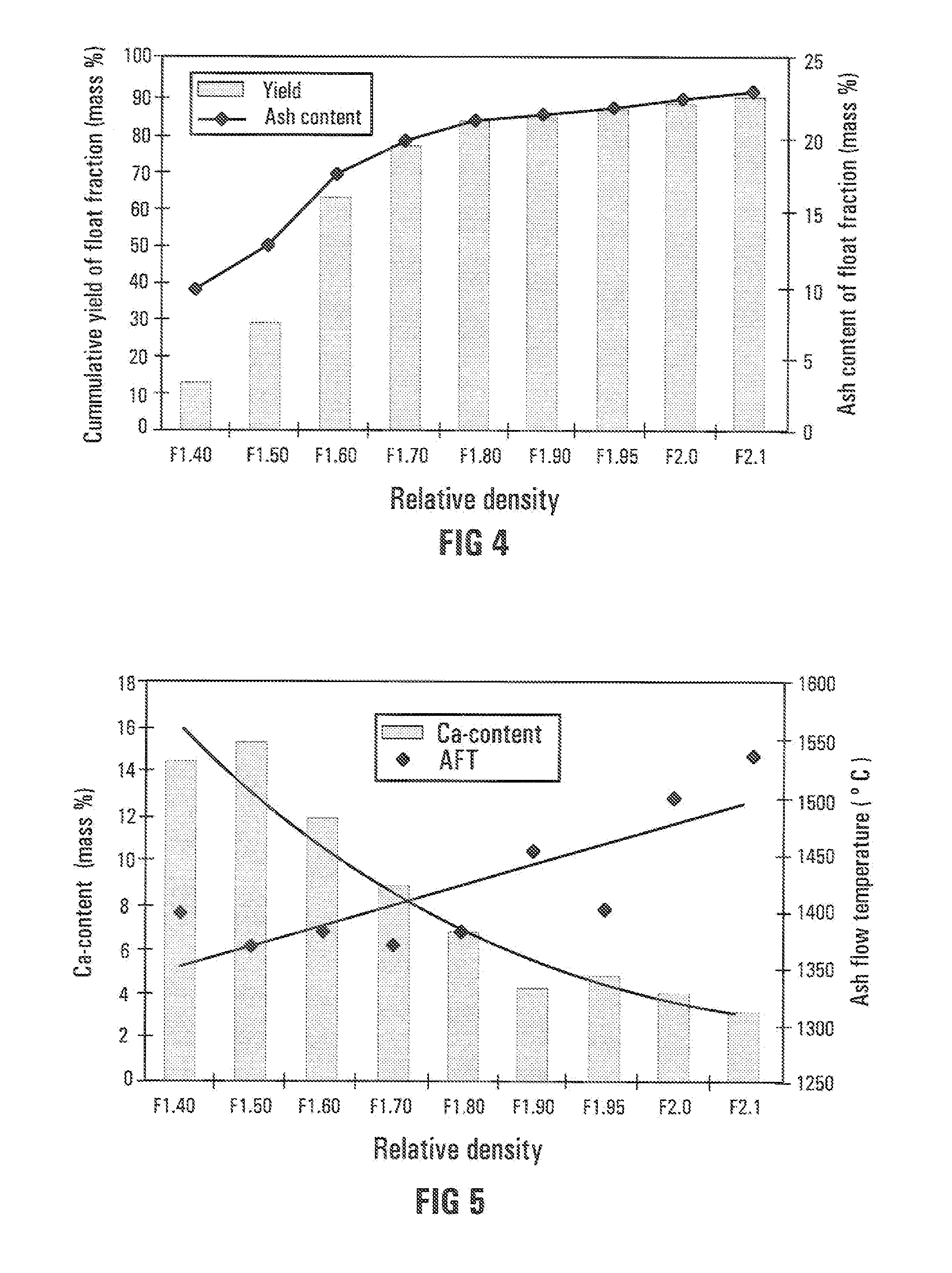
[0054]The same coal as was used in Example 1 was also the subject of investigation in Example 2. Dense media separation and ash and composition analysis provided the information as set out in more detail in Table 1 below.

TABLE 1DescriptionF1.40F1.50F1.60F1.70F1.80F1.90F1.95F2.0F2.1S2.1Yields12.5816.7634.0814.206.781.211.201.971.479.76Inh. H20%4.64.54.33.93.53.02.92.903.22.2Ash%9.514.621.729.239.446.852.152.205477Vol. Mat%28.623.922.020.317.816.415.815.8015.713Fix. Carbon%57.357.052.046.639.333.829.229.1027.17.8SiO2%36.8039.0045.7050.4054.4057.1057.7058.4063.359Al2O3%25.8025.5026.0026.5026.0025.2023.8025.7024.522.2Fe2O3%2.311.242.673.063.925.125.694.592.075.48P2O5%2.432.011.110.780.510.390.410.360.440.15TiO2%1.881.361.371.461.541.481.591.661.91.29CaO%14.4015.2011.908.776.754.134.733.923.175.11MgO%3.514.444.093.242.201.341.291.141.040.62K2O%0.590.570.660.830.810.840.840.840.961.14Na2O%1.020.780.570.420.370.270.250.290.260.15SO3%9.638.745.163.543.362.942.761.981.153.59

[0055]In Table 1,...


PUM

PropertyMeasurementUnit
temperatureaaaaaaaaaa
operating temperaturesaaaaaaaaaa

Abstract

A coal processing operation (10) includes in a dense media separation stage (12), subjecting a coal feedstock (18) which includes minerals to dense media separation producing a first coal stream (20) and a second coal stream (22). Coal in the first coal stream (20) is lower in ash and has a lower ash fusion temperature than coal in the second coal stream (22). Coal from the first coal stream (20) is processed in a high temperature coal processing operation (44), and coal from the second coal stream (22) is processed in a medium temperature coal processing operation (16).

Description

[0001]THIS INVENTION relates to a coal processing operation.[0002]Conventionally, blending and washing systems are employed to improve the quality of a run-of-mine coal feedstock before further processing of the coal, by reducing the mineral content of the coal feedstock. Blending and washing produce two product streams, namely a first de-mineralized stream low in mineral (ash) content for further use, typically in a single downstream process employing, for example, a particular gasification technology, and a second discard stream high in mineral content.[0003]The production of a discard stream is undesirable. The discard stream contains at least some coal (carbon) and the non use of this stream reduces the overall carbon efficiency of any process using the run-of-mine coal.[0004]According to the invention, there is provided a coal processing operation which includes[0005]in a dense media separation stage, subjecting a coal feedstock which includes minerals to dense media separation...

Claims


Application Information

Patent Timeline
Patent Type & Authority Applications(United States)
IPC IPC(8): C10J3/00
CPCC10J3/20C10J3/54C10L9/08C10J2300/093C10J3/721
Inventor VAN DYK, JOHANNES CHRISTOFFELWAANDERS, FRANS BOUDEWIJN
Owner SASOL TEKHNOLODZHI PROPRIEHJTEHRI LTD
Why Eureka
Try Eureka