
Apparatus for restoring waste plastic to oil

a technology of waste plastic and oil, applied in the field of apparatus for restoring waste plastic to oil, can solve the problems of waste plastic not being buried easily, not decomposing easily, and the disposal problem of waste plastic growing daily, so as to reduce pyrolysis gas, reduce waste plastic, and heat the decomposition space efficiently

Inactive Publication Date: 2011-05-26
ECO CREATION INDS
View PDF7 Cites 6 Cited by
  • Summary
  • Abstract
  • Description
  • Claims
  • Application Information

AI Technical Summary

Benefits of technology

[0007]Therefore, it is an object of the claimed invention to solve the aforementioned problems with the prior art apparatus. The claimed oil reduction apparatus for restoring or reducing plastics, preferably waste plastics, to oil comprises a decomposer to efficiently heat the decomposition space to pyrolyze the waste plastics partly before selectively heating the decomposition space and reducing pyrolyzed gas to oil by cooling. In accordance with an exemplary embodiment of the claimed invention, the decomposer selectively heats the decomposition space to pyrolyze the waste plastics based on the volume of the waste plastics in the decomposition space and continuously cooling the pyrolyzed gas produced from the pyrolyzed waste plastic to reduce the pyrolyzed gas to oil, thereby effectively increasing the reduction efficiency and reducing the process time required to reduce the waste plastics to oil.
[0010]In accordance with an exemplary embodiment of the claimed invention, the oil reduction apparatus further comprises a crusher to crush plastic, a crushing conveyor to move the crushed plastic from the crusher, and a storage tank to store the crushed waste plastic to be supplied to the decomposer. Preferably, the decomposer is located at one end of the crushing conveyor to receive the crushed plastic from the crushing conveyor. The utilization of the storage tank can shorten any potential producing delay by making the waste plastic crushed by the crusher readily available to the decomposer. That is, the decomposer does not have to wait for enough supply of crushed waste plastic. because the waste plastic is crushed in a crusher and reserved. Preferably, the storage tank can be positioned between the crushing conveyor and the decomposer to store the crushed plastic from the crusher to efficiently supply the decomposer to minimize any potential wait time for the decomposer.
[0021]In accordance with an exemplary embodiment of the claimed invention, the oil reduction apparatus continually performs the operation of crushing, pyrolyzing and oil reduction by cooling, thereby shorten the processing time, increasing the oil reduction efficiency, and minimizing gas losses. In accordance with an exemplary embodiment of the claimed invention, the decomposition space of the decomposer is partly heated to reduce the volume of plastic, preferably waste plastic, before pyrolyzing the waste plastic. By performing pyrolyzation on the heated waste plastic or heated decomposition space, the oil reduction apparatus can advantageously minimize the consumption of energy to pyrolyze the waste plastic. Also, after cooling the pyrolyzed waste plastic in the decomposer with a cooling air from the cooling part, the oil reduction apparatus of the claimed invention quickly cools the pyrolyzed gas to reduce it to oil, thereby greatly increasing the efficiency of the oil reduction process. That is, the oil is separated from the gas by the cooling water circulating in the cool space of the oil reduction body.
[0023]In accordance with an exemplary embodiment of the claimed invention, the oil reduction method cruses the plastic by a crusher to provide crushed plastic, transfers the crushed plastic to the decomposition space of the decomposer covered with a layer of insulation, and stores the crushed plastic in a storage tank to efficiently supply the decomposer.

Problems solved by technology

However, since plastic is a type of petroleum compound, mainly petroleum, it does not decompose easily.
But there are problems, particularly environmental problems, with plastic products after their use because they do not decompose easily.
The disposal problem associated with waste plastic is growing daily because of ever increasing use of plastic products.
The waste plastic cannot be buried easily because of its resolvability, it does not decompose readily like paper-based products.
When waste plastics are burned, various harmful gases are emitted, thereby polluting the air.
Handling waste plastic is a huge problem for everyone.
In addition, oil reserves including petroleum used in producing plastics are being rapidly depleted.
However, these currently available system are merely combination of various separate apparatuses and are problematic because of their slow processing speeds and low efficiency of converting waste plastic to oil.
Moreover, currently available apparatus for restoring waste plastic can be potentially hazardous to workers from the high temperature exhaust when the cover of the decomposer is opened.
To avoid such problem, the decomposer must be cooled for long time, thereby introducing processing delay and greatly reducing the conversion efficiency because subsequent waste plastic must wait until the decomposer is sufficiently cooled to be safely handled by the worker.

Method used


Image

  • Apparatus for restoring waste plastic to oil
  • Apparatus for restoring waste plastic to oil
  • Apparatus for restoring waste plastic to oil

Examples


Embodiment Construction

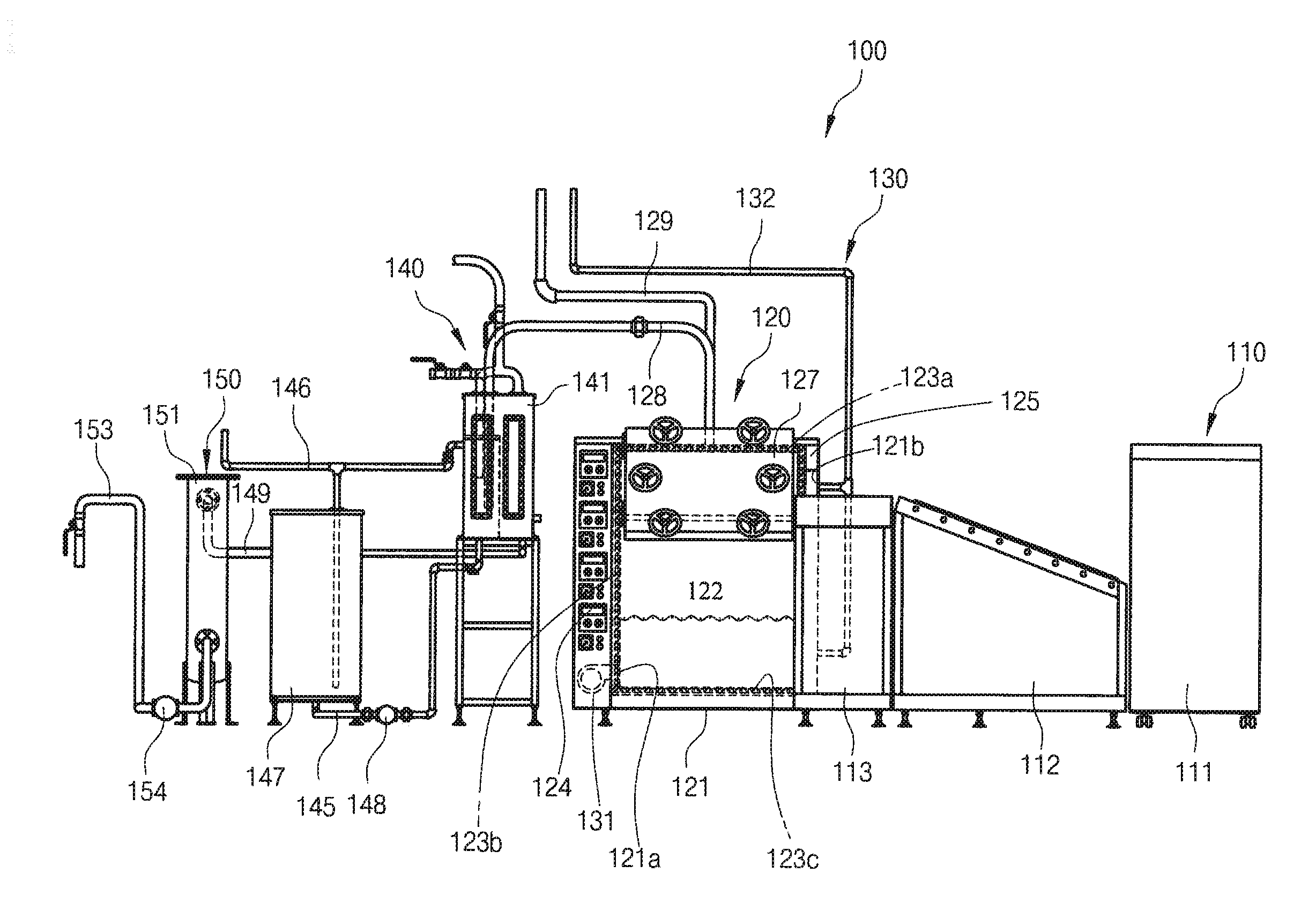
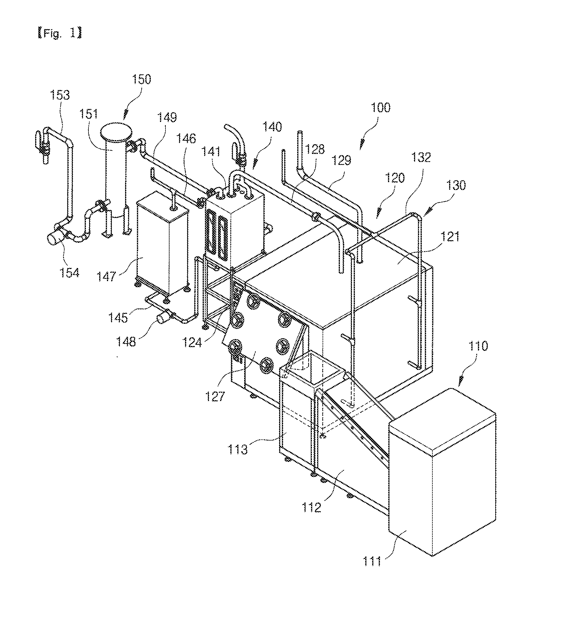
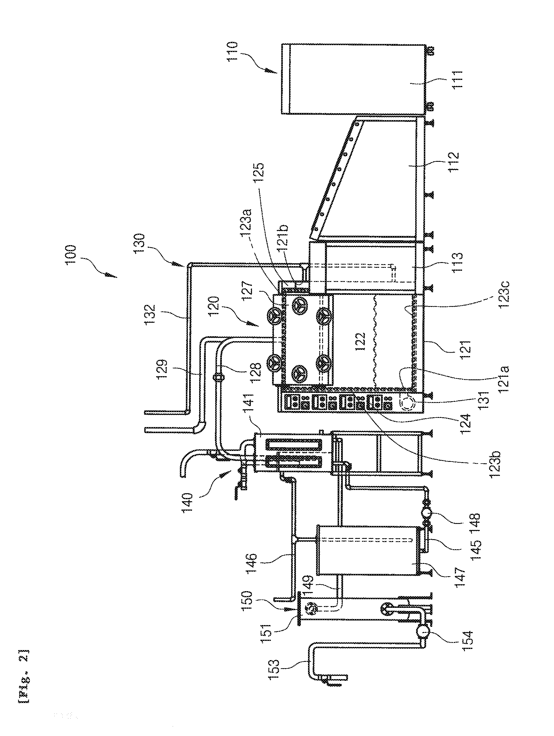
[0042]As exemplary shown in FIGS. 1-3, an apparatus (100) for restoring waste plastic to oil in accordance with an exemplary embodiment of the claimed invention comprises a crush producing part (110), a pyrolyzing part (120), a furnace cooling part (130), an oil reduction part (140), and a filter and emission part (150).

[0043]In accordance with an exemplary embodiment of the claimed invention, the crush producing part (110) comprises a crusher (111), a crushing conveyer (112) and a storage tank (113), as exemplary shown in FIGS. 4-5. The crusher (111) in accordance with an exemplary embodiment of the claimed invention is configured such that at higher position crushed waste plastic is produced by crushing the waste plastic from outside to inside. Preferably, the crusher (111) produces waste plastic towards the direction of the crushing conveyor (112). It is appreciated that any known crusher can be used with the claimed apparatus, and details of various known crushers are well known...


PUM

PropertyMeasurementUnit
areaaaaaaaaaaa
volumeaaaaaaaaaa
pressureaaaaaaaaaa

Abstract

The claimed invention relates to an apparatus and method for restoring plastic, to oil, thereby efficiently recycling waste plastic. The apparatus comprises a decomposer, an oil reduction body, a cooling tank, and a filter and emission part. The decomposer comprises a decomposition space comprising an opening to receive the plastic, a heating coil inside the decomposer to heat the decomposition space to pyrolyze the plastic, and a pyrolyzing gas exhaust pipe in an upper part of the decomposer connected to the decomposition space to exhaust pyrolyzing gas produced in pyrolyzing the plastic. The oil reduction body positioned in one side of the decomposer is divided into a cooling space and a oil catchment space by a partition. The cooling space is connected to the pyrolyzing gas exhaust pipe to receive the pyrolyzing gas from the decomposition space. The cooling tank positioned in one side of the reduction body provides cooling water to the cooling space to cool and reduce the pyrolyzing gas to oil, which is collected in the oil catchment space. The filter and emission part is positioned in another side of the reduction body and connected to the oil catchment space of the oil reduction body to filter the oil reduced from the pyrolyzing gas.

Description

RELATED APPLICATION[0001]This application claims priority from Korean Patent Application No. 2009-0113636 filed Nov. 23, 2009, which is incorporated herein by reference in its entirety.TECHNICAL FIELD[0002]The invention relates to an apparatus and method for restoring waste plastic to oil, thereby efficiently recycling waste plastic.BACKGROUND OF THE INVENTION[0003]Basically, plastic is resin product capable of being heated and pressurized. Plastic can be formed into various shapes by heating and pressurization. Plastic is also commonly known as synthetic resin. A final product made from plastic has a lot of molecular weight but it also has fluidity, so it is easy to produce various types of products from plastic. The main component of plastic is petroleum, so plastic can be produced by types of polymer. Depending on the users' needs, materials can be polymerized to produce a highly polymerized compound with various functions and characteristics. Hence, the use and popularity of pla...

Claims


Application Information

Patent Timeline
Patent Type & Authority Applications(United States)
IPC IPC(8): C10B53/07C10B27/00C10B57/00C10B57/04
CPCC10B47/02C10G1/10C10B53/07Y02P20/143B29B17/04
Inventor JEON, KI JEONG
Owner ECO CREATION INDS
Learn More