
Built-in antenna for headset

a headset and antenna technology, applied in the field of antennas, can solve the problems of low efficiency of chip antennas, abrupt change of sound quality of audio signals, and inability to meet demand, and achieve the effect of less affected and high efficiency

Inactive Publication Date: 2011-05-26
ACE TECH
View PDF8 Cites 8 Cited by
  • Summary
  • Abstract
  • Description
  • Claims
  • Application Information

AI Technical Summary

Benefits of technology

[0021]According to an embodiment of the present invention, audio signals may be sent and received with higher efficiency, without using a chip antenna, and the antenna may be less affected by such external factors as the hand effect and head effect.

Problems solved by technology

However, the chip antenna has a low efficiency of about −7 dB to −8 dB, and has the problem of causing the sound quality of audio signals to change abruptly if it is touched or moved by a hand.
In recent times, there has been an increasing demand for high sound quality for headsets, and such a demand could not be satisfied by the chip antenna, due to its low efficiency and abruptly changing receive sensitivity.

Method used


Image

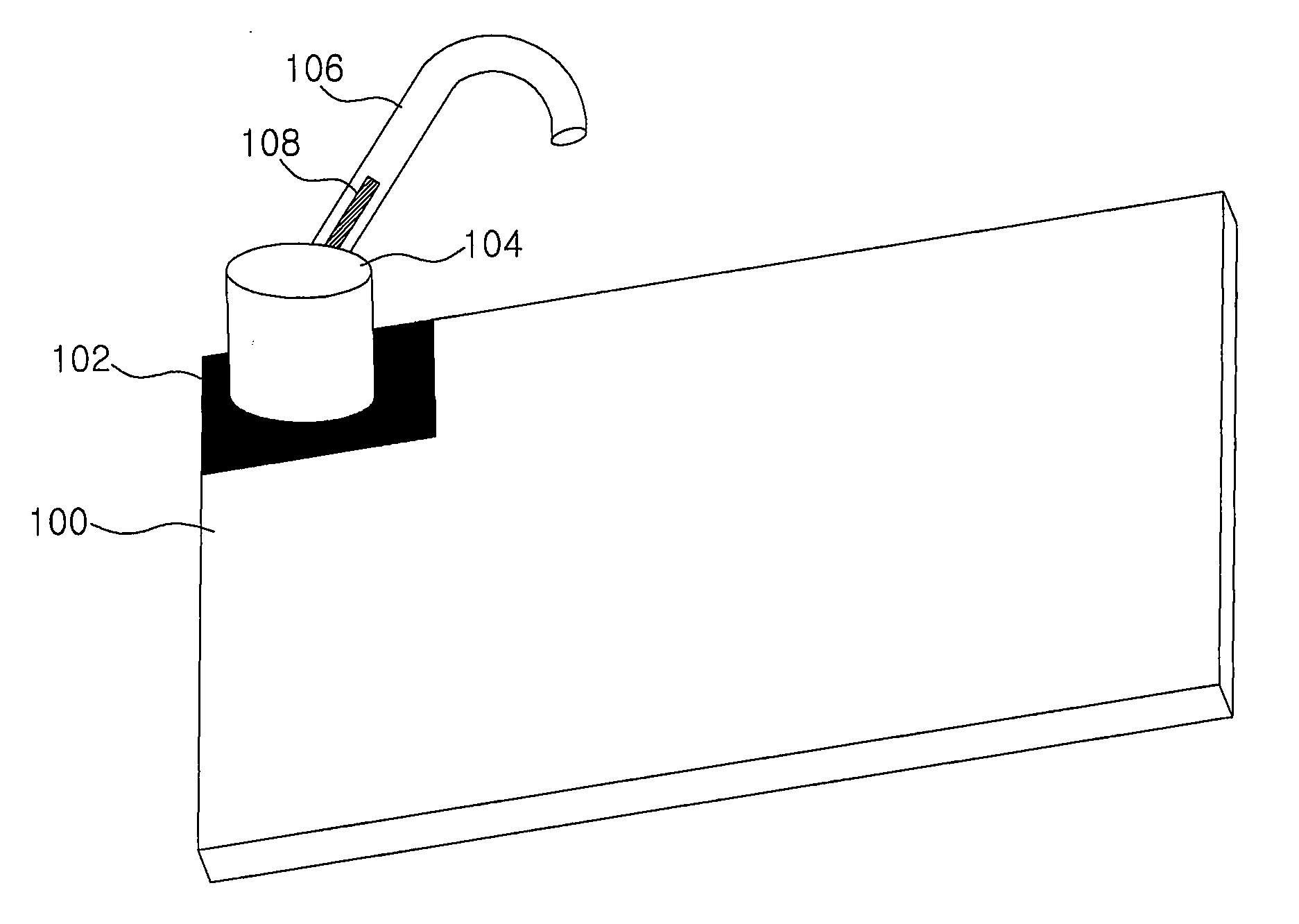
  • Built-in antenna for headset
  • Built-in antenna for headset
  • Built-in antenna for headset

Examples


second embodiment

[0053]In the embodiment illustrated in FIGS. 1 and 2, the connecting part 104 rotates while keeping electrical contact with the feeding pattern 102. Here, the electrical contact with the feeding pattern 102 may be destabilized by the rotation of the connecting part. The second embodiment illustrated in FIGS. 3 and 4 is an embodiment that improves on such instability of the electrical contact.

[0054]In FIGS. 3 and 4, the cylindrical feeding part 204 is electrically joined with the feeding pattern 102. The feeding part 204 is made of a metallic material. The feeding part 204 is set fixedly, not to rotate, and maintains electrical contact with the feeding pattern 202.

[0055]The rotational shaft 208 protrudes out of the upper part of the feeding part 204, to be mechanically joined with the connecting part 206.

[0056]As described above, the connecting part 206 is joined with the rotational shaft 208 at a particular distance away from the feeding part 204, and rotates if an external force is...

first embodiment

[0058]As in the first embodiment, the connecting part 206 has a joining groove 230 for joining the hooking part 210 to it, and the hooking part 210 is mechanically joined with the connecting part 206 by way of the joining groove 230. As described above, the hooking part 210 may be joined with the connecting part by a variety of joining methods, besides the joining groove method.

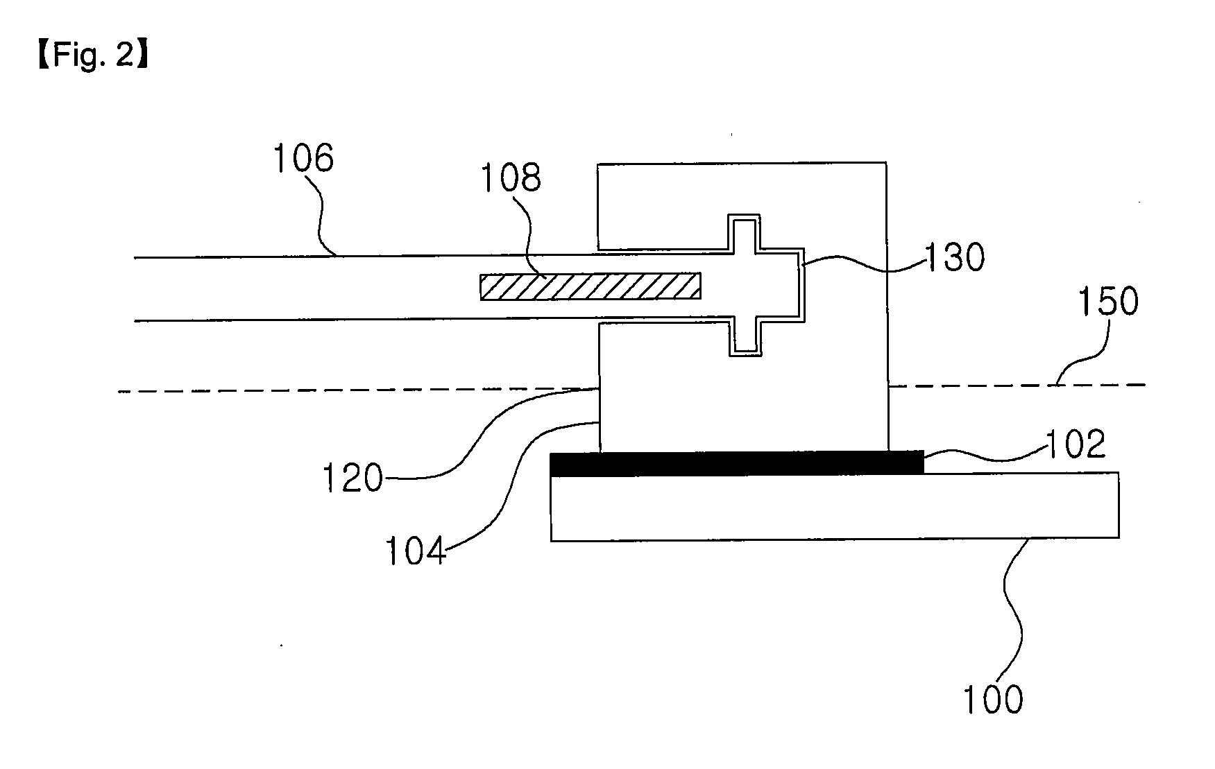
[0059]The radiator is inserted into the hooking part 210, and as described above, the radiator 212 may be inserted into the hooking part 210 by way of insert molding, for example.

[0060]The radiator, as in the first embodiment, may preferably be inserted in the area where the hooking part 210 and the connecting part 208 are joined.

[0061]Feeding from the connecting part 208 to the radiator 212 is done by a second coupling, and the radiator 212 radiates the RF signals fed or receives the RF signals transmitted from the outside.


PUM


Abstract

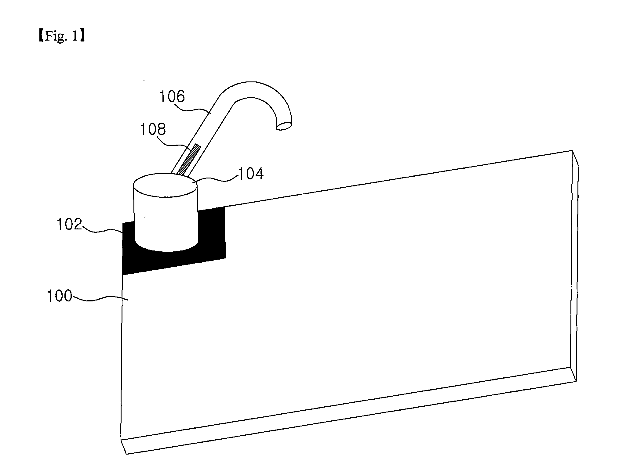
Disclosed is an internal antenna for a headset. The disclosed antenna comprises: a substrate, which is included inside a headset body; a feeding pattern formed on the substrate; a connecting part, which is made of a metallic material and electrically connected to the feeding pattern, and a portion of which protrudes into the housing of the headset body; a hooking part, which is joined with the connecting part; and a radiator, which is inserted into the hooking part. According to an embodiment of the present invention, audio signals may be sent and received with higher efficiency, without using a chip antenna, and the antenna may be less affected by such external factors as the hand effect and head effect.

Description

TECHNICAL FIELD[0001]The present invention relates to an antenna, more particularly to an antenna mounted inside a headset such as a Bluetooth headset device.BACKGROUND ART[0002]In recent times, wireless headsets have been in widespread use, appended to portable terminals such as mobile phones and MP3 players. Since wireless headsets exchange signals with such portable terminals as mobile phones and mp3 players, providing for their users the convenience of using such terminals without having to hold them directly in their hands, the use of wireless headsets is expected to continue to increase.[0003]Such wireless headsets mainly use the Bluetooth system, which is a representative communication system for local area networks in recent times, while communication can also be implemented through the DECT, binary CDMA systems.[0004]A wireless headset comprises: a headset body, which includes an antenna and a wireless chip, such as a Bluetooth chip, for wireless sending and receiving of au...

Claims


Application Information

Patent Timeline
Patent Type & Authority Applications(United States)
IPC IPC(8): H01Q1/22
CPCH04M1/05H01Q1/273H01Q1/2291H01Q1/24
Inventor KIM, BYONG-NAM
Owner ACE TECH
Learn More