Integrated laboratory light fixture

a laboratory light fixture and integrated technology, applied in the field of integrated laboratory light fixtures, can solve the problems of reducing the containment efficiency of hoods and other exhausted devices, affecting the operation of lighting support devices, so as to save building owners' money, eliminate installation and material handling costs, and retain connection costs

Inactive Publication Date: 2011-05-26
SHAMSHOIAN GARY PETER
View PDF53 Cites 23 Cited by
  • Summary
  • Abstract
  • Description
  • Claims
  • Application Information

AI Technical Summary

Benefits of technology

[0012]In accordance with a further embodiment, a fixture for suspended ceiling systems, comprising Sheetrock® (e.g. drywall or plaster wallboard) or other ceilings that improves overall above ceiling access by providing integral locations for many common ceiling mounted devices; a fixture that eliminates the design conflict between providing air supply and lighting over lab tables; a fixture that provides mounting points for room air and supply air temperature sensors, air quality sensors such as CO2, O2, VOC and other detectors, optical and acoustic sensors, radiation and other sensors, sprinkler heads, pressure ports, and environmental monitoring devices; another advantage of the present invention is the arrangement options for locations of electrical connections. The electrical power for the fixture can be connected on the top or the side of the fixture; the low profile and truncated corner edges enable the integrated lablight to be applied in installations with extreme space limitations.
[0013]In accordance with another embodiment, a fixture that saves building owner's money by: eliminating the installation and material handling costs of the air vent (connection costs are retained); minimizes air balancing and commissioning costs associated with non-optimized room level airflow patterns; generally reduces maintenance costs and maintenance response times by improving access to above ceiling devices; reducing costs for installing controls and sensors due to ceiling mounted location with no trim requirements a fixture that saves energy by minimizing airflow increases required for improving hood containment due to excessive room cross drafts, and by providing energy efficient lighting cooled by ceiling plenum air; low profile saves costs with less material used in fabrication; fixture material is predominantly recycled and recyclable; other applications include any room where airflow patterns are critical to the functioning of the facility; other applications include rooms where ceiling space is limited; other applications include rooms where ventilation and lighting are both needed in the same location.
[0014]In accordance with a further embodiment, a ceiling mounted fixture comprises: at least one longitudinal arrangement of at least one air vent adapted to receive an air supply; and at least two longitudinal arrangements of at least one light source, and wherein the at least one longitudinal arrangement of at least one air vent is positioned between the at least two longitudinal arrangements of light sources.
[0015]In accordance with another embodiment, a fixture comprises: a central light source; an air supply duct having a connection point in a center portion of the fixture; and a flow straightener, wherein the flow straightener routes an air supply through an adjustable flow splitter and around the central light source and out through a series of slots arranged symmetrically perpendicular to an axis of the fixture.
[0016]In accordance with a further embodiment, a ceiling mounted fixture system adapted to be located along a lab's central axis to create a sweeping airflow from a center portion of the lab to a perimeter thereof comprises: a plurality of linear fixtures comprising: a central light source; an air supply duct having a connection point in a center portion of the fixture; and a flow straightener, wherein the flow straightener routes an air supply through an adjustable flow splitter and around the central light source and out through a series of slots arranged symmetrically perpendicular to an axis of the fixture; and wherein the plurality of linear fixtures are aligned in a row along the center portion of the lab to maximize the overall room airflow patterns and ambient air mixing.
[0017]In accordance with another embodiment, a ceiling mounted fixture comprising: at least one longitudinal arrangement of at least one air vent, which receives an air supply; an air return located in a center portion of the fixture; and at least one light source.

Problems solved by technology

Ceiling space constraints often create difficult choices in controlled environment facilities because of competition for the optimum air outlet locations.
The competition for space with lighting and other ceiling devices may lead to imperfect air outlet locations and potentially undesirable large scale airflow patterns (eddies).
Many times the dynamic controls for the room HVAC (heating, ventilating and air-conditioning) system contributes to variable large scale airflow eddies which decrease the containment efficiency of hoods and other exhausted devices.
These eddies create cross drafts that impair proper hood functioning.
Usually, cross drafts require hood performance enhancements through increased exhaust and supply air flow rates, which lead to increases in energy costs.
The design engineers must address all of these concerns, but the equipment available today does not lead to easy solutions.
Once these considerations are addressed in high tech facilities, much of the ceiling tiles are no longer removable because of the devices rigidly mounted in them.
This leads to difficult compromises that impair above ceiling access and facility maintenance operations.
These inventions do not address the safety issues of hazardous compound containment devices (hoods and other exhausted cabinets) by promoting uniform room scale airflow patterns and minimizing cross drafts.
In addition, the energy efficiency of the lighting and airflow control has not been combined in other products currently available.

Method used


Image

  • Integrated laboratory light fixture
  • Integrated laboratory light fixture
  • Integrated laboratory light fixture

Examples


Embodiment Construction

[0028]Throughout the following description, specific details are set forth in order to provide a more thorough understanding of the invention. However, the invention may be fabricated without these particulars. In other instances, well known elements have not been shown or described in detail to avoid unnecessarily obscuring the invention. Accordingly, the specification and drawings are to be regarded in an illustrative, rather than a restrictive, sense.

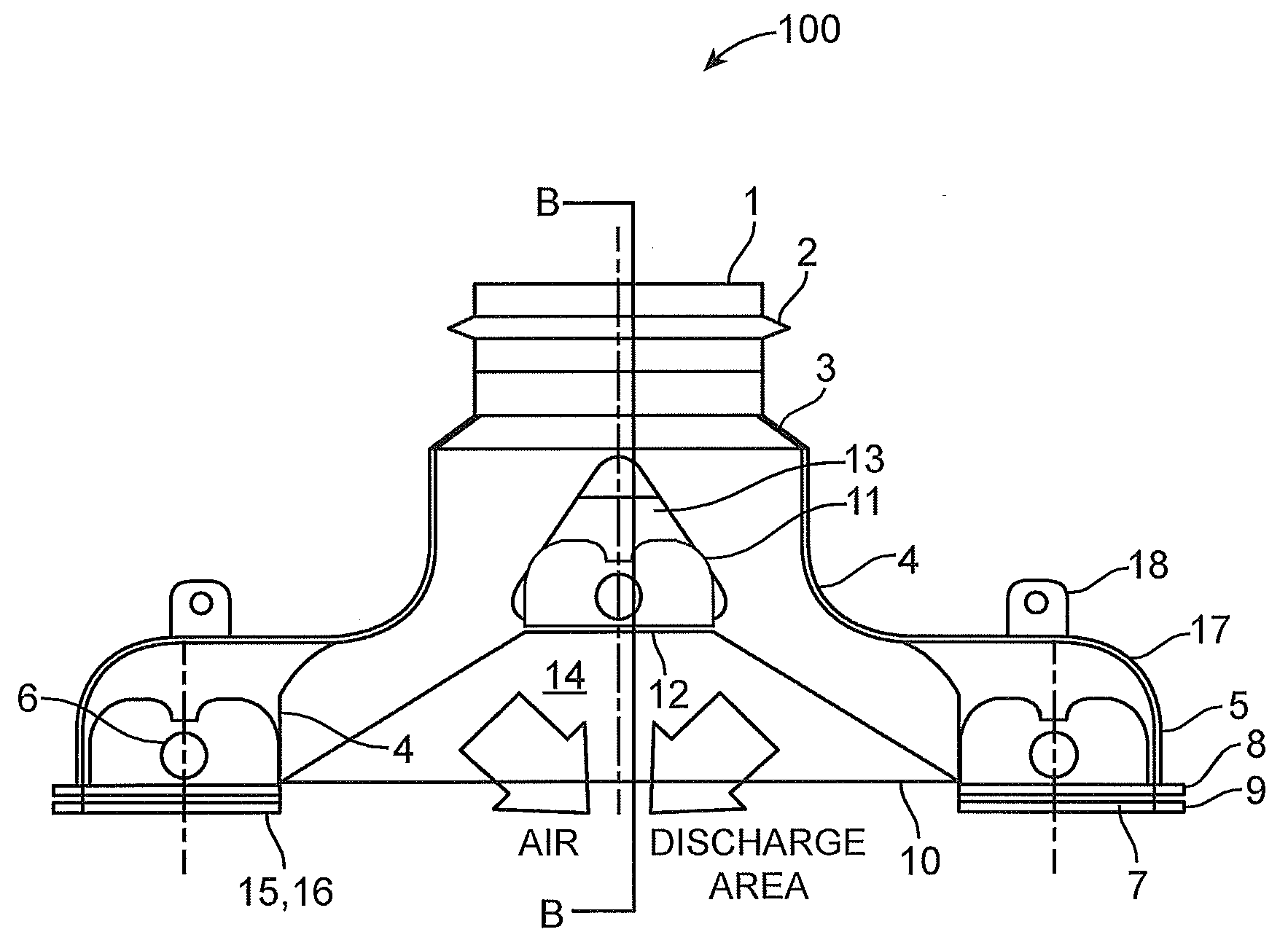
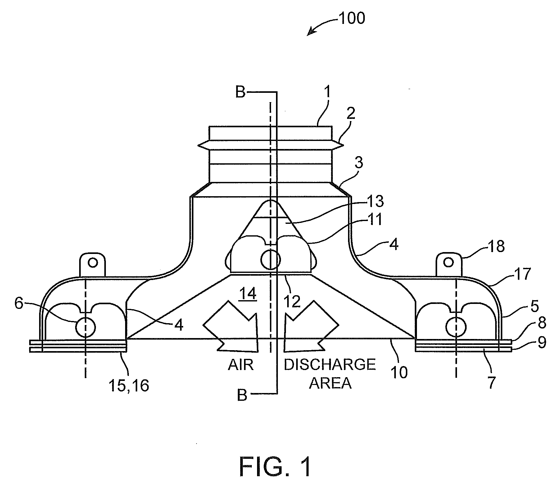
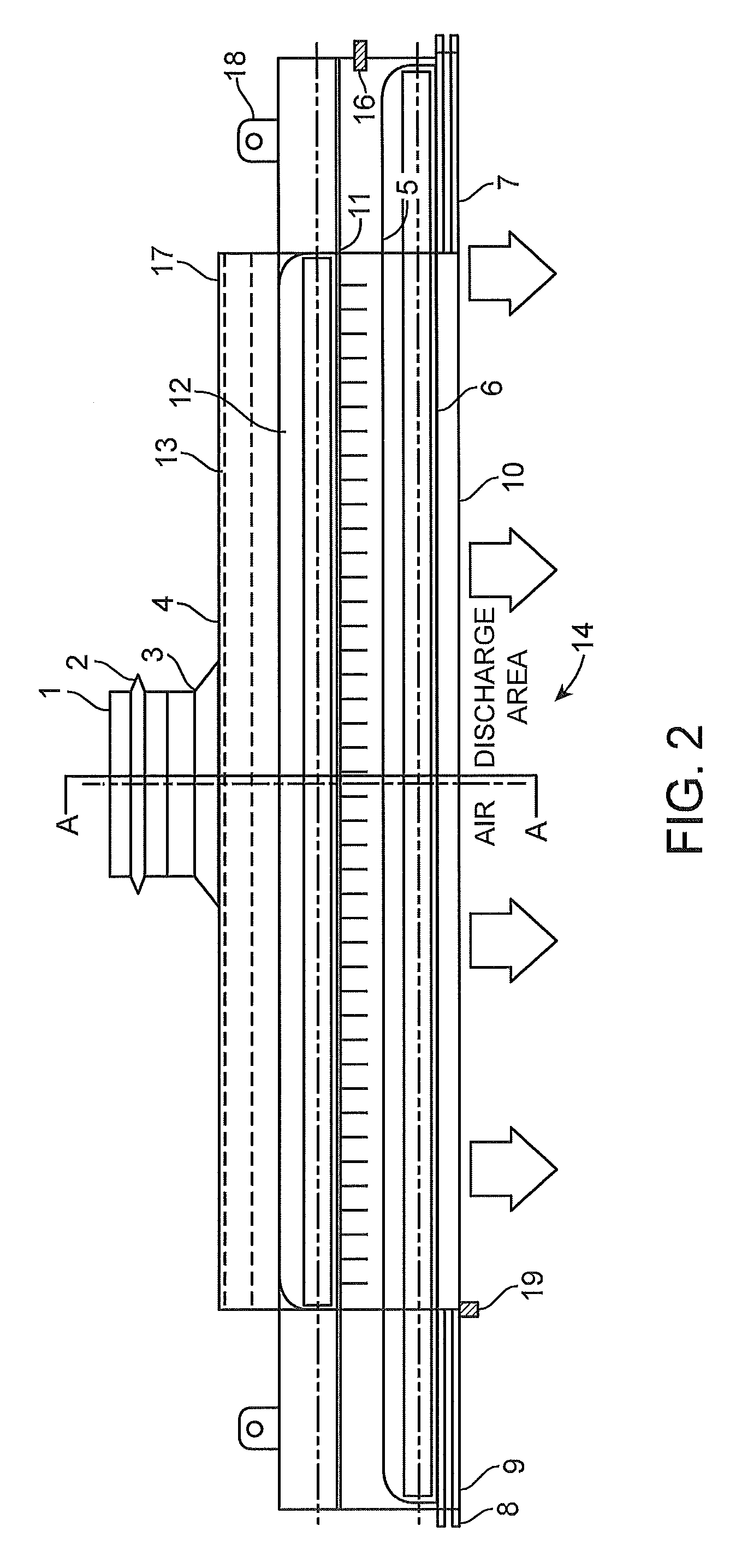
[0029]The integrated laboratory light fixture 100 may take form in various components and arrangements of components, and in various steps and arrangements of steps. Slight modifications and variations to fit specific needs of designers are included in this invention. The drawings are only for purposes of illustrating a preferred embodiment and are not to be construed as limiting the invention.

[0030]The integrated lablight combines lights and HVAC air outlets to promote lab safety by minimizing hood cross drafts. Usage of the fixture...


PUM


Abstract

The integrated laboratory light (lablight) fixture is a sealed ceiling mounted fixture that combines air outlets, lighting and other devices for use in laboratory, clean room, healthcare, educational, and other facilities requiring critical airflow control. The integrated lablight is made for a central location in the lab to eliminate room scale eddies and cross drafts along with the hood challenges they present. The combining of most ceiling devices in one fixture results in a safer environment with greater access for above ceiling maintenance, as well as less expensive facility capital costs. The fixture design also minimizes shadows at the work surface, and promotes temperature stability for temperature sensitive equipment.

Description

CROSS-REFERENCE TO RELATED APPLICATIONS[0001]This patent application is a continuation-in-part of U.S. patent application Ser. No. 11 / 520,437, filed Sep. 12, 2006, which claims priority to U.S. Provisional Patent Application No. 60 / 716,045, filed Sep. 12, 2005, and which are incorporated herein by reference in their entirety.FIELD OF THE INVENTION[0002]The present invention relates to an integrated laboratory light fixture, which combines a light, an air vent, and other device fixtures for use in a suspended ceiling grid or Sheetrock® (e.g. drywall or plaster wallboard) system, and more particularly to an integrated laboratory light fixture design that promotes safety in facilities with critical airflow pattern requirements (such as labs, pharmaceutical, food, medical and healthcare applications), and reduces facility capital, energy and operating costs.BACKGROUND OF THE INVENTION[0003]Suspended ceiling systems are extensively used throughout the construction industry, both in new b...

Claims


Application Information

Patent Timeline
Patent Type & Authority Applications(United States)
IPC IPC(8): F21V29/00F21S4/00F21V7/00F21S8/04
CPCE04B9/02F24F13/078F21V33/0088
Inventor SHAMSHOIAN, GARY PETER
Owner SHAMSHOIAN GARY PETER
Why Eureka
Try Eureka