Turbine vane and gas turbine

a technology of gas turbines and turbines, which is applied in the direction of engine fuction, machine/engine, stators, etc., can solve the problems of increasing the amount of cooling air for the entire blade, difficult to carry out appropriate film cooling, and likely to overcool the suction surface ss side of the body, etc., to achieve the effect of suppressing insert deformation and improving film cooling properties

Active Publication Date: 2011-05-26
MITSUBISHI HEAVY IND LTD
View PDF13 Cites 77 Cited by
  • Summary
  • Abstract
  • Description
  • Claims
  • Application Information

AI Technical Summary

Benefits of technology

[0031]The present invention has been made to solve the above-described problems, and an object thereof is to provide a turbine vane and a gas turbine that realize appropriate impingement cooling for a body by selecting appropriate pressure difference between insert spaces and pressure-surface-side cavity spaces and between insert spaces and suction-surface-side cavity spaces, and that can improve the cooling properties of film cooling for an airfoil part by suppressing deformation of inserts.

Problems solved by technology

Therefore, it is likely to excessively cool the suction surface SS side of the body, compared with the pressure surface PS side thereof.
However, when only one insert 81 is provided in each cooling chamber, it is difficult to carry out appropriate film cooling.
In other words, the amount of air used for impingement-cooling the suction surface SS becomes excessive with respect to the pressure surface PS, the suction surface SS of the body is excessively cooled, and the amount of cooling air for the entire blade is increased, thus reducing the cooling efficiency of the gas turbine.
However, when the number of impingement holes on the suction surface SS of the body is reduced more than the number of impingement holes on the pressure surface PS of the body, the pitch of impingement holes is increased at the suction surface SS of the body, thus causing a temperature variation in the body and increasing the thermal stress on the body.
However, these methods of improving the strength of the insert cause a problem in manufacturability of the inserts.

Method used


Image

  • Turbine vane and gas turbine
  • Turbine vane and gas turbine
  • Turbine vane and gas turbine

Examples


Embodiment Construction

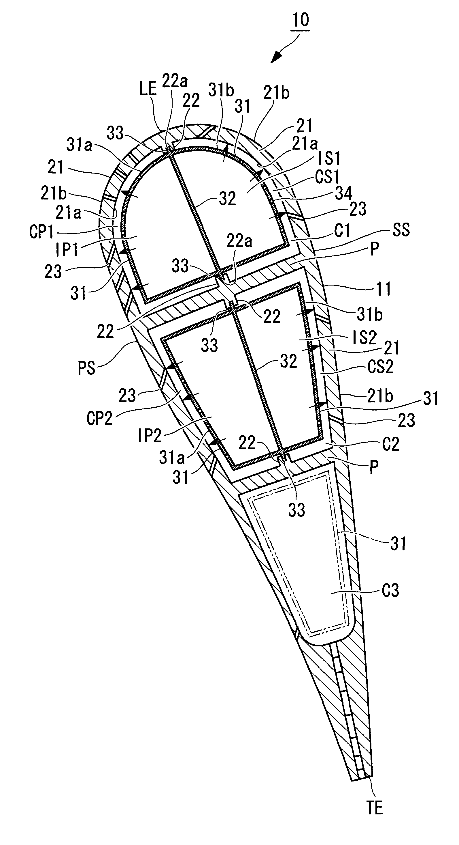
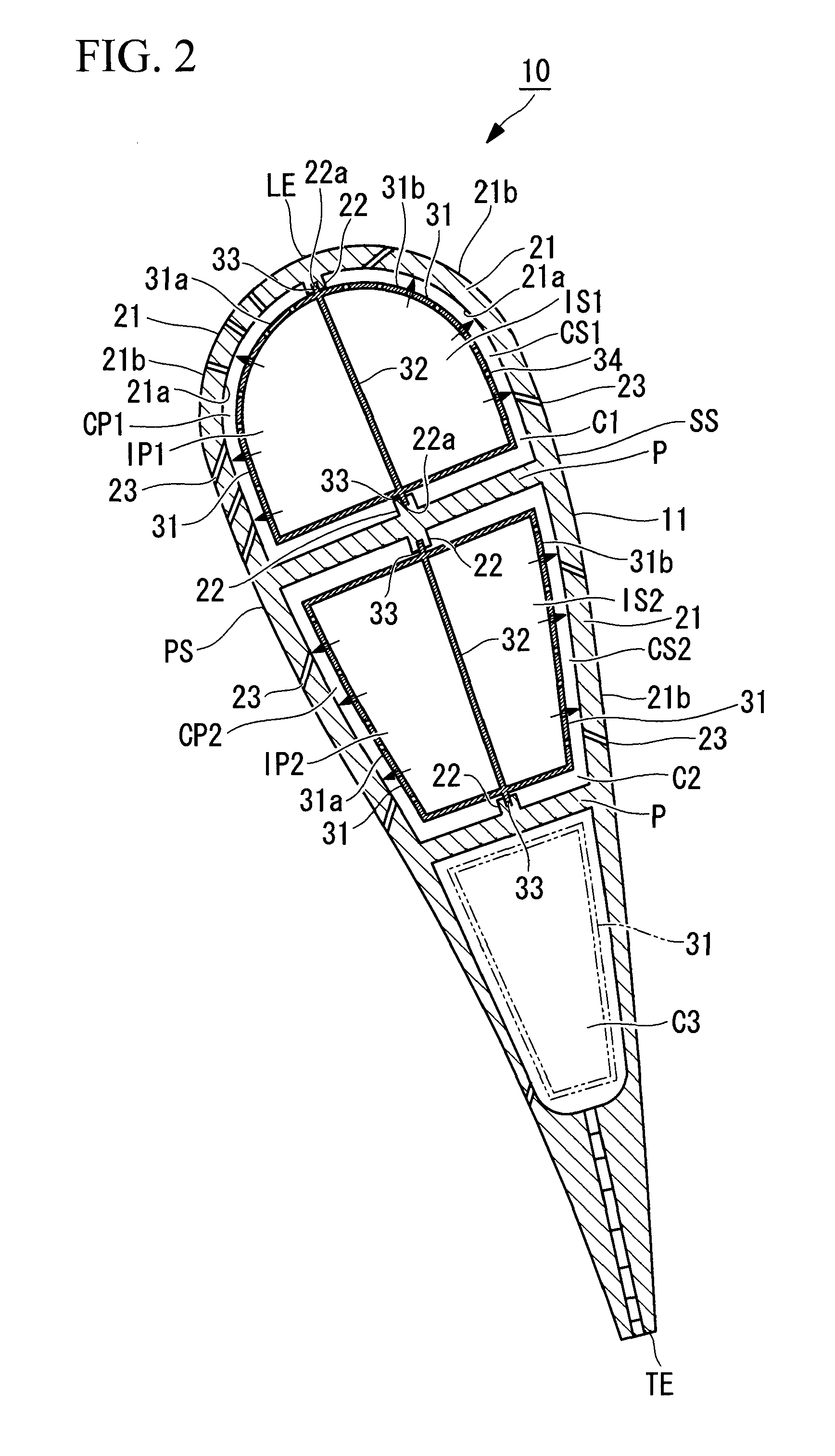
[0055]The configurations of a turbine vane and a gas turbine according to a first embodiment of the invention will be described with reference to FIGS. 1 to 3. Note that, in this embodiment, a description will be given of a case where the configuration of the turbine vane of the present invention is applied to a first-stage vane or a second-stage vane in a turbine section of a gas turbine.

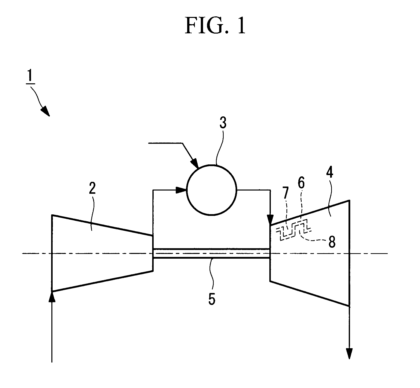
[0056]FIG. 1 is a schematic diagram for explaining the configuration of the gas turbine having the turbine vane according to this embodiment. As shown in FIG. 1, a gas turbine 1 includes a compression section 2, a combustion section 3, a turbine section 4, and a rotary shaft 5.

[0057]As shown in FIG. 1, the compression section 2 takes air in from the outside, compresses it, and supplies the compressed air to the combustion section 3. Upon reception of a rotary driving force transferred from the turbine section 4 via the rotary shaft 5, the compression section 2 is rotationally driven, thereby taking...


PUM


Abstract

An airfoil part includes a plurality of cooling chambers that are spaces into which the inside of the airfoil part is partitioned, from a leading edge side to a trailing edge side, by a partition wall, that extend in a vane-longitudinal-section direction, and that include division parts on inner walls of a body; insert cylinders that are disposed in the cooling chambers and that have a plurality of impingement holes; and film holes that are provided in the body. The insert cylinders include partitioning parts that extend from the leading edge side to the trailing edge side and that extend in the vane-longitudinal-section direction. The insides of the insert cylinders are partitioned into pressure-surface-side insert spaces close to a pressure surface and suction-surface-side insert spaces close to a suction surface.

Description

CROSS REFERENCE TO RELATED APPLICATIONS[0001]This application claims benefit of Japanese Application No. 2009-114641 filed in Japan on May 11, 2009, the contents of which is hereby incorporated by its reference.BACKGROUND OF THE INVENTION[0002]1. Field of the Invention[0003]The present invention relates to a turbine vanes having a cooling structure in a gas turbine and to a gas turbine.[0004]2. Description of Related Art[0005]In general, turbine blades and turbine vanes in gas turbines usually include cooling structures therein because they are used in high-temperature environments.[0006]A known example for cooling turbine vanes is a configuration in which two or three cavities through which cooling air passes are provided and inserts (insert cylinders) are disposed in these cavities (see U.S. Pat. No. 4,312,624, Japanese Unexamined Patent Application, Publication No. 2002-161705, Japanese Unexamined Patent Application, Publication No. 2003-286805, and Japanese Unexamined Patent App...

Claims


Application Information

Patent Timeline
Patent Type & Authority Applications(United States)
IPC IPC(8): F01D5/18
CPCF01D5/189F05D2240/12F05D2260/30F05D2260/202F05D2260/201F01D9/065F01D9/02F01D25/12
Inventor HADA, SATOSHITSUKAGOSHI, KEIZO
Owner MITSUBISHI HEAVY IND LTD
Why Eureka
Try Eureka