Fuel container for fuel cell

a fuel cell and container technology, applied in electrochemical generators, transportation and packaging, packaging goods types, etc., can solve the problems of uneven coating layer, peeling off the coating layer, and uneven coating layer, so as to reduce the amount of the partitioning member can slide smoothly, and the pressure needed to extrude the remaining fuel can be set low.

Inactive Publication Date: 2011-05-26
TOKAI
View PDF2 Cites 1 Cited by
  • Summary
  • Abstract
  • Description
  • Claims
  • Application Information

AI Technical Summary

Benefits of technology

[0034]The frictional force generated at the surfaces of a connector main body and a partitioning member, which are in sliding contact, of a fuel container for fuel cells having a structure as described above, is 10N or less. Therefore, the partitioning member can slide smoothly. If the sliding properties of the partitioning member are improved in this manner, the partitioning member is enabled to move with little pressure. Therefore, when the amount of fuel stored within a fuel storage chamber becomes low, the amount of pressure necessary to extrude the remaining fuel can be set low. That is, the internal pressure within an extruding means housing chamber when the volume of the extruding means housing chamber is maximal can be set low. By setting the internal pressure in this state to be low, the internal pressure of the extruding means housing chamber when the fuel storage chamber is filled to the maximum with fuel, that is, when the volume of the fuel storage chamber is maximal and the volume of the extruding means housing chamber is minimal, can also be set low. Therefore, the volume ratio of the fuel storage chamber with respect to the container main body can be set to be high. In addition, if the pressure is low, the need to form the walls of the container main body to be thick is obviated. Therefore, the volume of the container main body and the volume of the fuel storage chamber are not decreased. Accordingly, a greater amount of liquid fuel can be contained in the fuel container.
[0035]A coating layer constituted by a polyparaxylene resin having non-eluting properties with respect to the liquid fuel may be provided on at least one of the surfaces of the connector main body and the partitioning member which are in sliding contact. In this case, the coating layer may be formed without spraying, thereby decreasing the risk that the coating layer will be peeled off. Accordingly, the partitioning member can operate positively, without becoming inclined during movement, or the movement thereof becoming erratic. Therefore, the sliding properties of the partitioning member are improved, and failure rates are reduced, by securing positive sliding characteristics, sufficient durability, and sealing properties of the partitioning member. In addition, by reducing the failure rate, the possible number of repeated use increases.
[0036]The coating layer may be formed to have a film thickness within a range of 0.2 μm to 3 μm. In this case, the properties of the material of the partitioning member can be fully taken advantage of, due to the thinness of the coating layer, and leakage of the liquid fuel can be prevented.

Problems solved by technology

Therefore, unevenness occurs in the coating layers.
The unevenness causes wrinkles to be generated in the coating layers following repeated use of the partitioning members, and there is a possibility that further use will peel the coating layers off.
In the case that the coating layers are partially peeled off, the partitioning members becomes inclined during operation, or the operation thereof becomes erratic.
If these defects occur, there is a possibility that leaks and the like will occur, in addition to the operating defects of the partitioning members.
If leaks occur, the durability of the partitioning members suffers, and the possible number of reuse of the fuel containers as a whole becomes limited.
Therefore, the aforementioned leaks are highly likely to be the extruding means (compressed gas) leaking into the fuel storage chamber, which causes gas to be mixed into the liquid fuel.
There is also a slight possibility of the liquid fuel leaking into the extruding means housing chamber.
Generally, in the case that the coating layers are thick, the properties of the material of partitioning members cannot be fully taken advantage of.
In the case that the coating layers are excessively thin, it is known that as the number of repeated uses increases, the probability that the coating layers will be peeled off due to friction increases.
The film thickness of the coating layers formed in the aforementioned manner is approximately 20 μm, and it is difficult to form them to be any thinner.

Method used


Image

  • Fuel container for fuel cell
  • Fuel container for fuel cell
  • Fuel container for fuel cell

Examples


embodiment 1

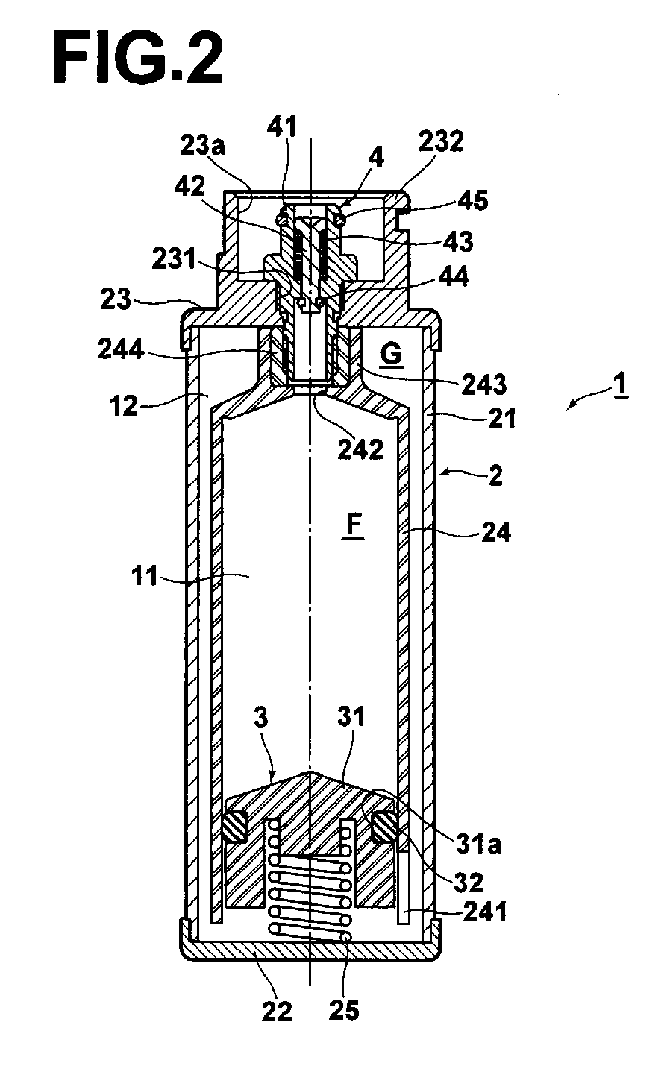
[0118]An endurance test was performed, utilizing the inner container 24, the partitioning member 3 (main body 31 and the O-ring 32), and the valve 4 as described in the above embodiment. The inner container 24 and the main body 31 were molded from PP, the O-ring was molded from EPDM, with a coating layer of parylene N having a film thickness of 1 μm.

[0119]1) First, the partitioning member 3 was positioned at the topmost portion of the inner container 24. The valve 4 was mounted into the aperture 242, and 2 ml of pure methanol was injected into the inner container 24. Thereafter, the partitioning member 3 was pressed from below, to expel the pure methanol via the valve 4. This operation was repeated twice, to expel gas from within the inner container 24.

[0120]2) Next, 6 ml of a mixture of purified water at 70% by weight and methanol at 30% by weight was injected into the inner container 24 via the valve 4.

[0121]3) After injection, the valve 4 was removed. Then, the partitioning membe...

embodiment 2

[0128]The same fuel container as that of Embodiment 1 was utilized to perform a test of deterioration over time. The testing method comprised steps 1 and 2 of the durability test above. Thereafter, the fuel container was left to stand in a 65° C. environment for a predetermined amount of time, at which point step 3 was performed.

[0129]5) After the value of frictional force was measured, the valve 4 was replaced, and the 30% methanol by weight solution was injected into the inner container 24 via the valve 4, thereby returning the fuel container to a state after step 2 of the durability test. Thereafter, the fuel container was left to stand in a 65° C. environment again for a predetermined amount of time, at which point step 3 was performed.

[0130]Step 5 was repeatedly performed, to measure changes in the sliding frictional force with the passage of time that the fuel container was left standing in the 65° C. environment. Note that the “Time Left Standing” in this test refers to the c...

embodiment 3

[0136]The same fuel container as that of Embodiment 1 was utilized to perform a test of seal failure. The testing method comprised steps 1 and 2 of the durability test above. Then, the 30% by weight methanol solution was caused to flow out via the valve at a rate of 6 ml / 60-120 min. Thereafter, the number of fuel containers in which gas had entered due to seal failure of the O-ring was counted.


PUM

PropertyMeasurementUnit
frictional forceaaaaaaaaaa
thicknessaaaaaaaaaa
thicknessaaaaaaaaaa

Abstract

A fuel container for fuel cells is equipped with a container main body, containing liquid fuel therein to be supplied to a fuel cell, equipped with a connecting port, for connecting with the fuel cell or a pressure adjusting device, and extruding means, for extruding the liquid fuel. The fuel container is also equipped with a partitioning member, which is slidably provided within the container main body, for partitioning the interior of the container main body into a fuel storage chamber, in which the liquid fuel is contained, and an extruding means housing chamber, in which the extruding means is housed. The fuel container is further equipped with a valve provided in the connecting port, for enabling or preventing the flow of the liquid fuel. The frictional force generated at the surfaces of the connector main body and the partitioning member, which are in sliding contact, is 10N or less.

Description

BACKGROUND OF THE INVENTION[0001]1. Field of the Invention[0002]The present invention relates to a fuel container for fuel cells that houses liquid fuel for fuel cells, such as Direct Methanol Fuel Cells (DMFC's) and supplies the liquid fuel to the fuel cells. The present invention relates particularly to a partitioning member within the fuel container that partitions the liquid fuel and an extruding means for extruding the liquid fuel.[0003]2. Description of the Related Art[0004]Recently, the use of fuel cells in miniature portable terminals, such as laptop computers and Personal Digital Assistants (PDA's), is being considered. Fuel containers (fuel cartridges, for example) have been proposed as a means of supplying fuel to the fuel cells.[0005]Liquid fuels, such as mixtures of purified water and methanol, and mixtures of purified water and ethanol, are considered as fuels to fill the fuel containers.[0006]It is desired that fuel supply pumps, remaining fuel amount detecting mechan...

Claims


Application Information

Patent Timeline
Patent Type & Authority Applications(United States)
IPC IPC(8): H01M8/02
CPCH01M8/04186H01M8/04208Y02E60/50H01M8/1011H01M8/1009B65B3/00H01M8/04H01M8/10
Inventor NAKAMURA, YASUAKIUSUI, HIDETOKOMIYAMA, SATOSHIHIROTOMI, MITSUO
Owner TOKAI
Why Eureka
Try Eureka