Method of Manufacturing Semiconductor Device

Active Publication Date: 2011-05-26
SAMSUNG ELECTRONICS CO LTD
View PDF8 Cites 14 Cited by
  • Summary
  • Abstract
  • Description
  • Claims
  • Application Information

AI Technical Summary

Benefits of technology

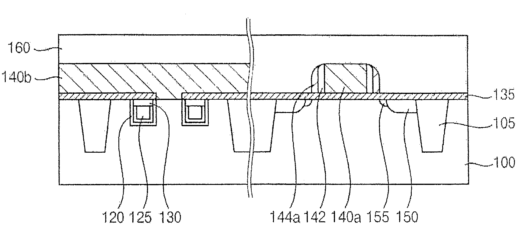
[0041]According to some embodiments, a highly doped impurity region may be formed prior to forming a lightly doped impurity region for manufacturing an LDD using an OSS. Since the lightly doped impurity region is formed later, the thickness of a spacer remaining on a side wall of a gate electrode may be reduced. In addition, an overlapping capacitance may be decreased, because the substrate under the bottom portion of the gate electrode and the impurity doped region may not overlap, or an overlapping area thereof may be reduced. Accordingly, a semiconductor device having improved electric characteristics may be manufactured.

Problems solved by technology

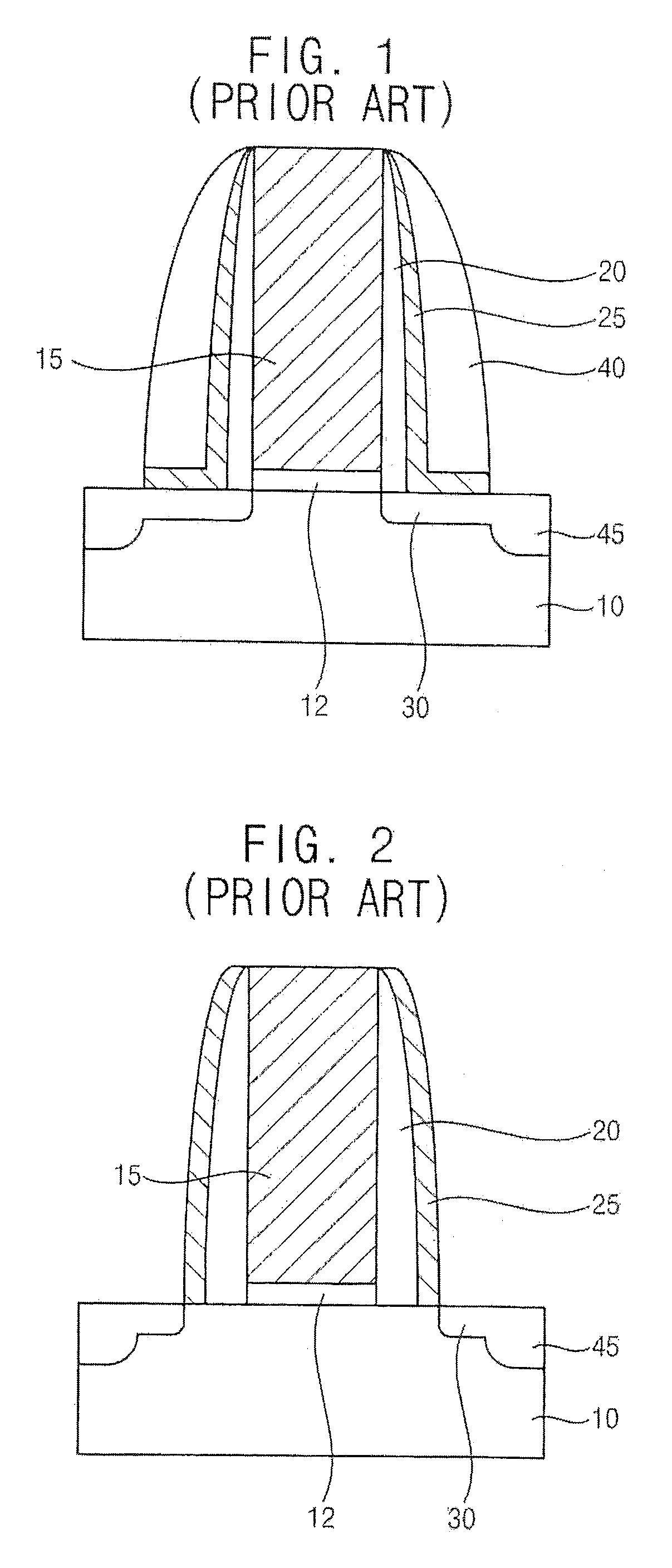
Generally, as semiconductor devices become more highly integrated, short channel effects in MOS transistors have become more problematic.
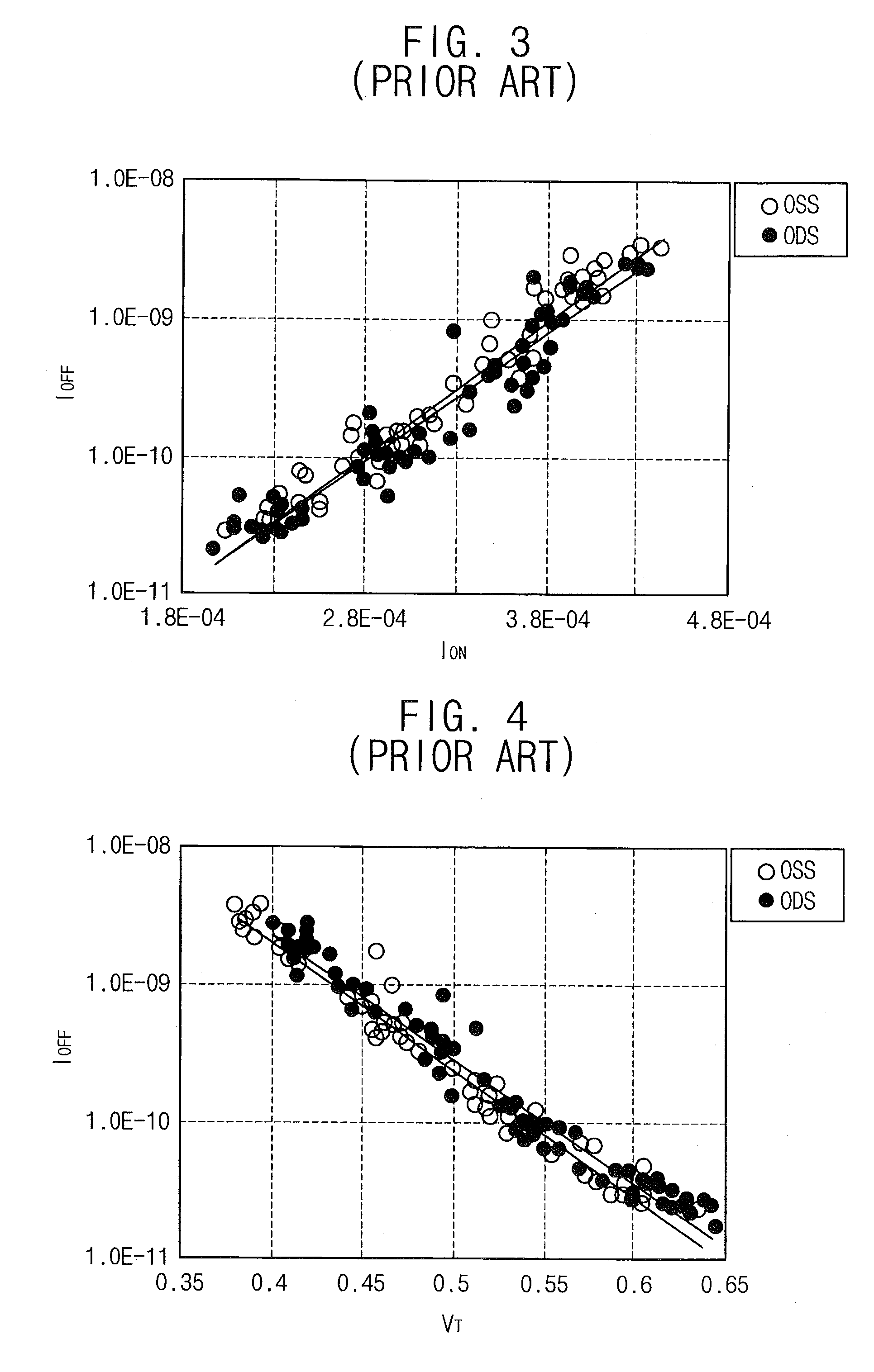
However, the LDD structures show a very large difference in electric characteristics.
However, for manufacturing a dynamic random access memory (DRAM), commonly applicable processes for manufacturing a MOS transistor having an LDD structure using an OSS structure may be very complicated.

Method used


Image

  • Method of Manufacturing Semiconductor Device
  • Method of Manufacturing Semiconductor Device
  • Method of Manufacturing Semiconductor Device

Examples


Embodiment Construction

[0067]Various example embodiments will be described more fully hereinafter with reference to the accompanying drawings, in which some example embodiments are shown. The present inventive concept may, however, be embodied in many different forms and should not be construed as limited to the example embodiments set forth herein. Rather, these example embodiments are provided so that this description will be thorough and complete, and will fully convey the scope of the present inventive concept to those skilled in the art. In the drawings, the sizes and relative sizes of layers and regions may be exaggerated for clarity.

[0068]It will be understood that when an element or layer is referred to as being “on,”“connected to” or “coupled to” another element or layer, it can be directly on, connected or coupled to the other element or layer or intervening elements or layers may be present. In contrast, when an element is referred to as being “directly on,”“directly connected to” or “directly ...


PUM


Abstract

Methods of manufacturing a semiconductor device include forming a gate electrode on a semiconductor substrate, forming spacers on side walls of the gate electrode, and doping impurities into the semiconductor substrate on both sides of the spacers to form highly doped impurity regions. The spacers are selectively etched to expose portions of the semiconductor substrate, and more lightly doped impurity regions are formed in the semiconductor substrate between the highly doped impurity regions and the gate electrode.

Description

CLAIM OF PRIORITY[0001]This application claims priority under 35 USC §119 to Korean Patent Application No. 10-2009-0114439, filed on Nov. 25, 2009 in the Korean Intellectual Property Office (KIPO), the disclosure of which is herein incorporated by reference in its entirety.BACKGROUND[0002]Some embodiments relate to methods of manufacturing a semiconductor device. More particularly, some embodiments relate to methods of manufacturing a semiconductor device including a metal oxide semiconductor (MOS) transistor having a reduced overlapping capacitance.[0003]Generally, as semiconductor devices become more highly integrated, short channel effects in MOS transistors have become more problematic. In order to reduce the prevalence of short channel effects, source / drain regions of MOS transistors have been formed to have a lightly doped drain (LDD) structure.[0004]FIG. 1 illustrates an LDD structure formed by using an offset dual spacer (ODS).[0005]The LDD structure illustrated in FIG. 1 ma...

Claims


Application Information

Patent Timeline
IPC IPC(8): H01L21/336
CPCH01L27/10852H01L27/10873H01L27/10876H01L27/10894H01L28/91H01L29/66628H01L29/4966H01L29/517H01L29/6653H01L29/6659H01L29/495H10B12/05H10B12/053H10B12/09H10B12/033H10B99/00H10B12/00
Inventor KIM, SUNG-HWANSATORU, YAMADA
Owner SAMSUNG ELECTRONICS CO LTD
Why Eureka
Try Eureka