Apparatus, method, and program for optimization model analysis

a technology of optimization model and program, applied in multi-objective optimisation, instruments, cad techniques, etc., can solve the problem of increasing the weight of the design model, and achieve the effect of reducing the thickness of the optimization model

a technology of optimization model and program, applied in multi-objective optimisation, instruments, cad techniques, etc., can solve the problem of increasing the weight of the design model, and achieve the effect of reducing the thickness of the optimization model

US20110125464A1Inactive Publication Date: 2011-05-26AISIN AW CO LTD +1

Image

  • Apparatus, method, and program for optimization model analysis
  • Apparatus, method, and program for optimization model analysis
  • Apparatus, method, and program for optimization model analysis

Examples


Embodiment Construction

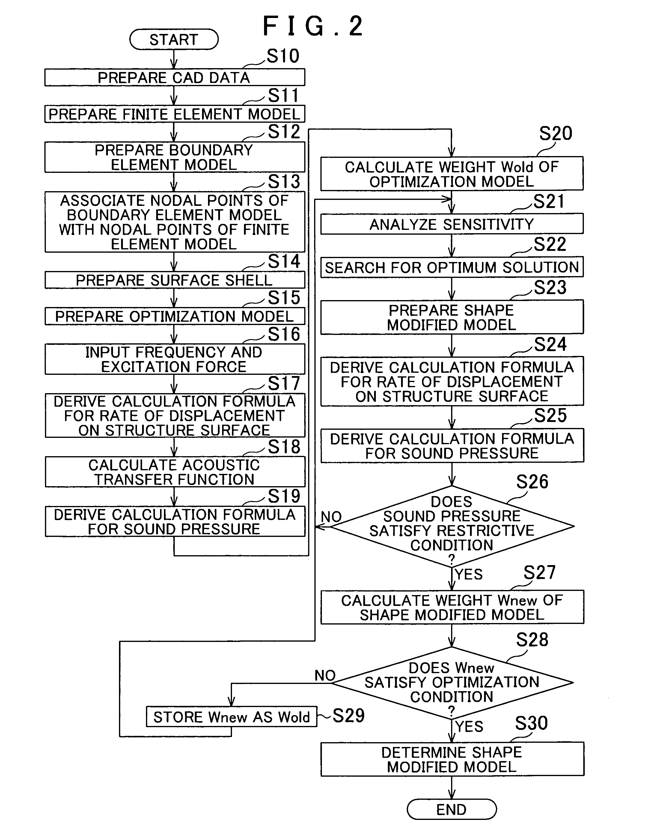
[0022]An embodiment of the present invention will be described below with reference to FIGS. 1 to 7.

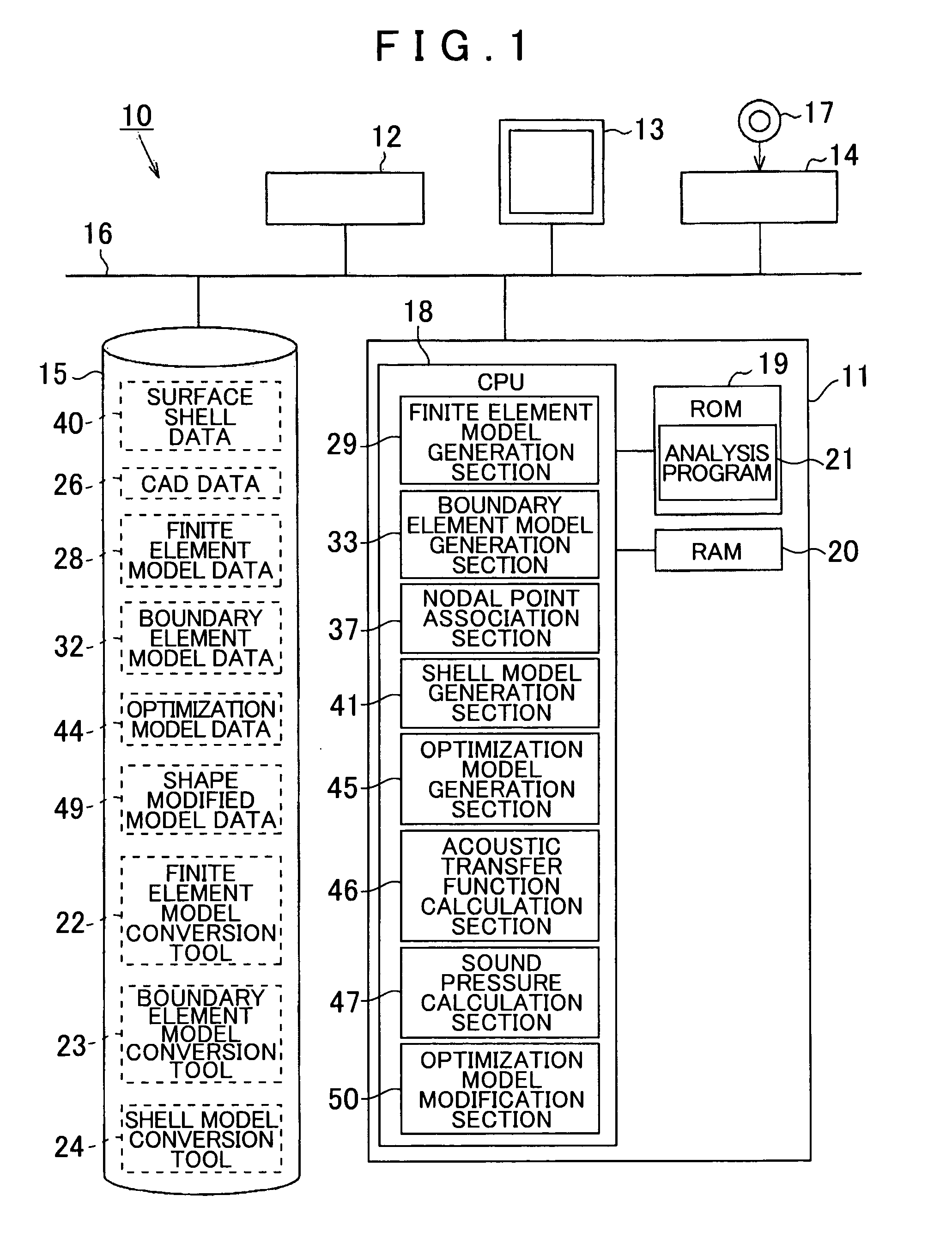
[0023]As shown in FIG. 1, a computer system 10 according to the embodiment includes a control device 11, an input device 12, an output device 13, a reader device 14, and a disk device 15. In the computer system 10, the respective devices 11 to 15 are connected via a bus 16 to enable transfer of information between each other. The devices 11 to 15 are thus configured to serve as an optimization model analysis apparatus that can perform various information processes.

[0024]A storage medium 17 such as a CD (Compact Disc) is insertable into and removable from the reader device 14. In the embodiment, a storage medium 17 storing CAD data on the structural configuration of a design model to be analyzed, a storage medium 17 storing finite element model conversion software for use to convert the CAD data into a finite element model, a storage medium 17 storing boundary element model conversion ...


PUM


Abstract

An optimization model analysis apparatus configured with a finite element model generation unit that generates on the basis of a structural configuration of a design model having a 3D shape a finite element model for analyzing acoustic characteristics of the design by a finite element method. The apparatus is configured with a shell model generation unit that generates a model by dividing a surface of the finite element model into a plurality of plate elements having a polygonal shape; an optimization model generation unit that superimposes the shell model on the surface of the finite element model to generate an optimization model; and an optimization model modification unit that displaces nodal points which serve as vertexes of the plate elements in a direction intersecting a plane of the plate elements by displacing at least one of the nodal points in a direction of reducing a thickness of the optimization model.

Description

INCORPORATION BY REFERENCE[0001]The disclosure of Japanese Patent Application No. 2009-266726 filed on Nov. 24, 2009 including the specification, drawings and abstract is incorporated herein by reference in its entirety.BACKGROUND OF THE INVENTION[0002]The present invention relates to an apparatus, a method, and a program for optimization model analysis that are used to determine through analysis an optimum structural configuration of a design model.DESCRIPTION OF THE RELATED ART[0003]In the related art, in determining through analysis an optimum structural configuration of a design model to optimize the acoustic characteristics, for example, of the design model, the structural characteristics and the acoustic characteristics of the design model are first individually analyzed on a computer through numerical simulation that uses a numerical analysis program. Then, a designer takes the analysis results into comprehensive consideration to specify a structural portion that is effective...

Claims


Application Information

Patent Timeline
26 May 2011
Publication
US20110125464A1
IPC
G06F17/50
CPC
G06F17/5018; G06F2217/08; G06F17/5095; G06F30/15; G06F30/23; G06F2111/06
Inventors
IDE, TAKANORI; KITAJIMA, HIROYUKI