Laser sensor based system for status detection of tires

a technology of state detection and laser sensor, which is applied in vehicle tyre testing, instruments, roads, etc., can solve the problems of unbalance of tires, vibration, and influence on laser output properties, and achieves simple and cost-effective effects

Inactive Publication Date: 2011-06-02
KONINKLIJKE PHILIPS ELECTRONICS NV
View PDF9 Cites 40 Cited by
  • Summary
  • Abstract
  • Description
  • Claims
  • Application Information

AI Technical Summary

Benefits of technology

[0003]It is an objective of the current invention to provide a simple and cost effective system for measuring tire parameters.

Problems solved by technology

Laser sensors based on self-mixing interferometry (SMI) make use of the effect that laser light, which is thrown back from the surface of the tire and reenters the laser cavity, interferes with the resonating radiation and thus influences the output properties of the laser.
The vibrations might be induced by unbalance of the tire or by irregularities of a surface where the tire is rolling on.
Focusing the laser light on the surface of the tire increases the resolution of the laser sensor, while a parallel beam of laser light needs no refocusing and may prevent problems related to a fixed focus distance since auto-focussing to focus the surface of the tire independently of the distance may be possible, but seems to be rather costly and probably prone to error.

Method used


Image

  • Laser sensor based system for status detection of tires
  • Laser sensor based system for status detection of tires
  • Laser sensor based system for status detection of tires

Examples


Embodiment Construction

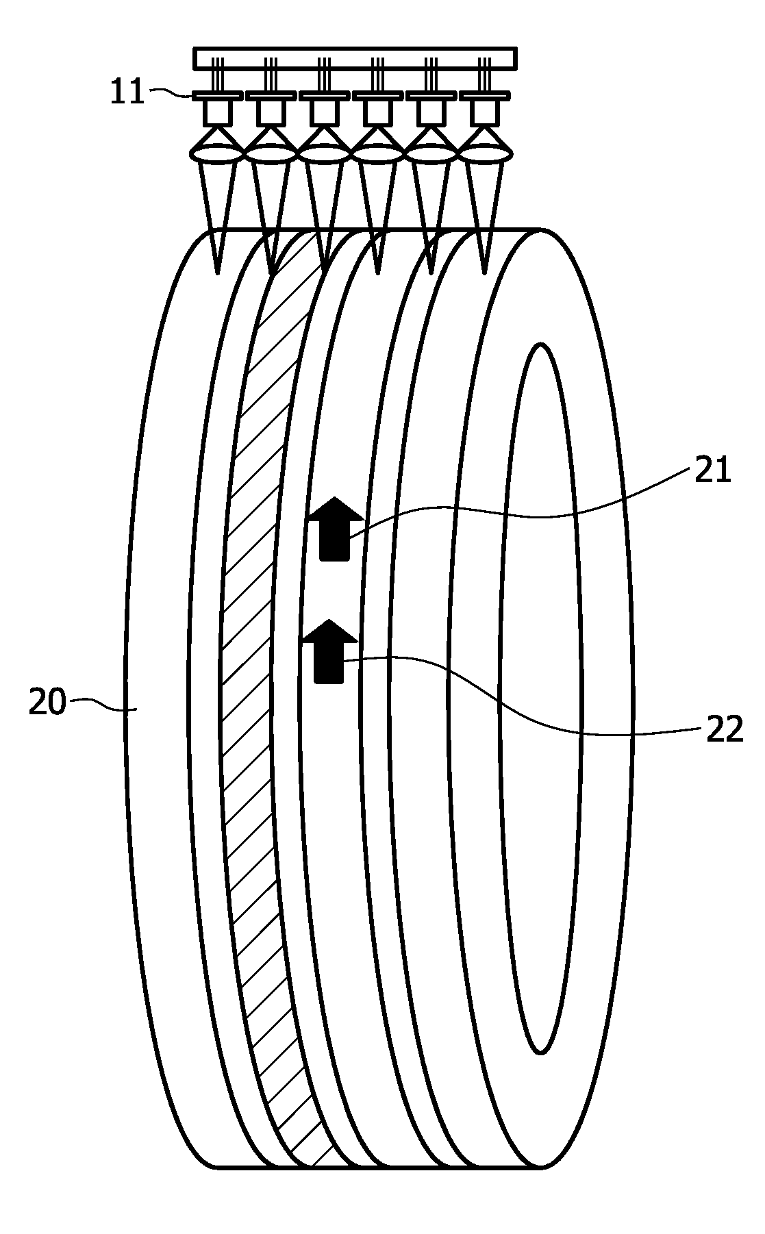
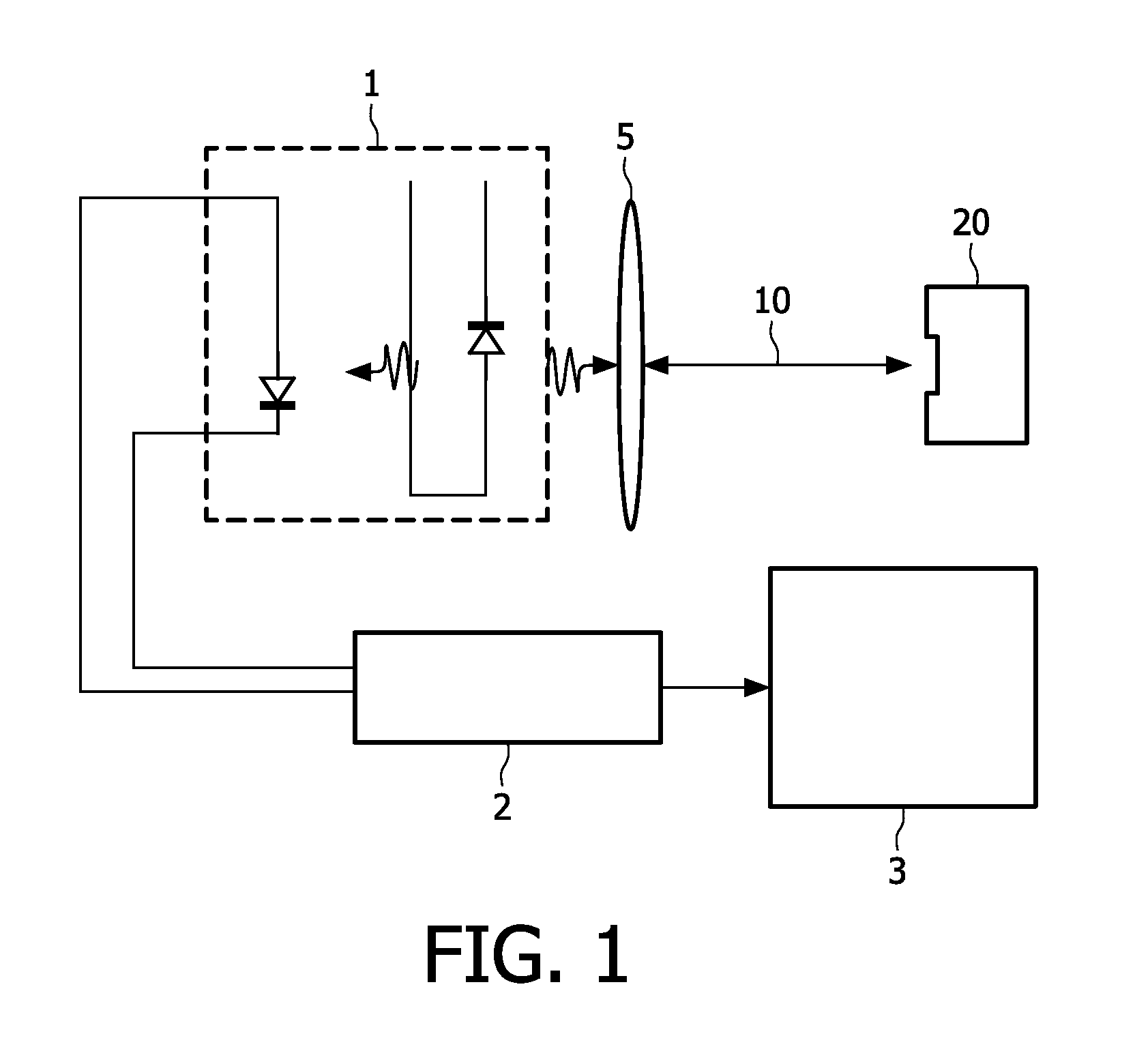
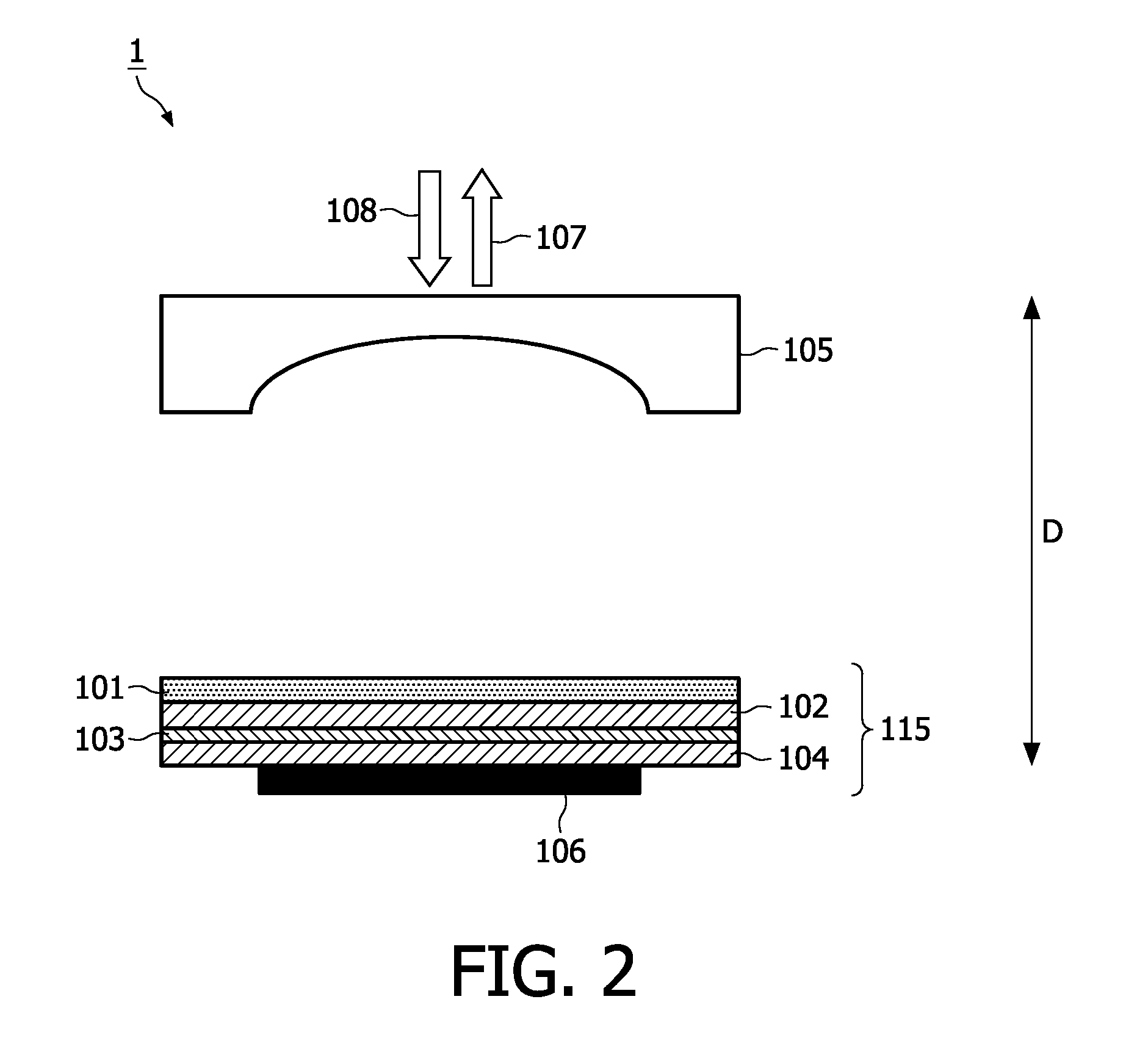
[0034]FIG. 1 shows a schematic view of an embodiment according to the current invention. The laser sensor 1 comprises a laser diode as a side emitter, a VCSEL or VECSEL and a photo detector. The laser diode emits laser light 10. A lens 5 is used to focus the laser light 10 on the surface of the tire or to collimate the laser light 10 in a parallel beam. The laser light 10 is thrown back by the surface or part of the surface of a tire 20. The thrown back laser light is focused on the laser cavity by means of the lens 5, re-enters the laser cavity and interferes with the resonating light in the laser cavity, resulting in variations of the resonating light, which are detected by means of the photo detector. The detected variations of the resonating light in the laser cavity are converted to electrical signals by means of the photo detector, analyzed by the analyzer 2 in the form of a processor and finally indicated by an indicator 3 in the form of a screen in a car informing a driver a...


PUM


Abstract

A system is described which enables parameters of a tire (20) to be measured by means of self-mixing laser interferometry. Laser sensors (1) using self-mixing laser interferometry can measure distances and / or speed of surface elements of a tire (20). Consequently, a system comprising such a laser sensor (1) can for example be used to measure and indicate tire tread wear, tire load or speed. In comparison with laser sensor based systems using the well-known time of flight method, the described system is simple, cost effective and, due to the small size of the laser sensor (1), can easily be integrated in cars.

Description

FIELD OF THE INVENTION[0001]The current invention is related to a laser sensor based system for measuring tire parameters, the use of such a laser sensor based system for measuring tire tread wear, tire load, or vehicle speed, and a laser based method of measuring tire parameters.BACKGROUND OF THE INVENTION[0002]In EP 0547365 B1, a method and apparatus for measuring tire parameters is disclosed. The tread wear of a tire can be circumferentially measured by means of the described apparatus. A laser probe sequentially scans each of the ribs of a tire, obtaining data regarding the tread depth at various points along the ribs. This data is employed for each rib to determine heel-to-toe irregular wear of the lugs thereof and also to determine a total wear index indicative of the degree of wear of the lugs. The method and apparatus are also adapted to laterally scan the tire sidewall to obtain data for ascertaining any anomalies thereof. The movement of the tire has to be defined and tigh...

Claims


Application Information

Patent Timeline
Patent Type & Authority Applications(United States)
IPC IPC(8): G01M17/02
CPCB60C23/068G01B9/02092G01B9/02027B60C11/246
Inventor BENGOECHEA APEZTEGUIA, JAIONEMOENCH, HOLGER
Owner KONINKLIJKE PHILIPS ELECTRONICS NV
Why Eureka
Try Eureka