Assembly and method for subsea well drilling and intervention

a technology for subsea wells and assemblies, applied in the direction of drilling pipes, wellbore/well accessories, sealing/packing, etc., can solve the problems of large drillships not being able to travel through such waterways, limiting the locations in which they can travel, and becoming impractical to use such platforms, etc., to save a casing string size, high pressure integrity, and high pressure environment

Inactive Publication Date: 2011-06-02
STENA DRILLING
View PDF14 Cites 23 Cited by
  • Summary
  • Abstract
  • Description
  • Claims
  • Application Information

AI Technical Summary

Benefits of technology

[0008]Floatable structures used in deepwater drilling and intervention are provided as embodiments of the present invention. The systems and methods described herein allow operators to perform MPD, UBD, or TTRD) in deep water applications. In an exemplary embodiment, the floatable structure includes a dual BOP system comprising an upper blow out preventer (“UBOP”) and a lower blow out preventer (“LBOP”). The UBOP is located between a drill floor and above a riser string, while the LBOP is located below the riser string and above a wellhead. The riser utilizes a slim design adapted to withstand a high pressure environment. The UBOP, LBOP, and riser combine to form a riser system that has the same high pressure integrity from top to bottom, essentially forming an extension of the wellbore. In addition, an expandable intermediate liner may be tripped down the riser and installed below a slim surface casing, thus saving a casing string size. Also, the present invention allows the well to be designed to effectively reduce the number of casing strings by using MPD or UBD drilling technology.

Problems solved by technology

As the water becomes deeper, however, use of such platforms becomes impractical.
In addition, the physical size and height of the drilling derrick or other type of hoisting tower of the ship also limits the locations in which it can travel.
For example, large drillships may not be able to travel through such waterways as the Suez or Panama Canals due to height constraints across the canals, and likewise may not be able to travel under the bridge in the Bosphorous (mouth of the Black sea) due to the height of their drilling derricks or hoisting tower on the drillship.
It is often necessary to travel around such waterways, which greatly increases the travel costs and time.
In addition, conventional deepwater rigs cannot efficiently perform some advanced drilling operations.
The conventional deepwater rigs that utilize a single subsea blowout preventer (“BOP”) on the seabed which is tied back to the drillship with a relatively low pressure marine riser that is not designed to withstand closed in internal pressure (designed for flow only) lack the pressure integrity in the riser to routinely carry out either MPD nor UBD due to the marine risers' lack of internal pressure integrity (typically a 21¼ inch marine riser has a burst pressure at the time of manufacture of approximately 1,000 psi, which cannot be field tested during the riser's life-time).
Limited MPD is also performed where a rotating control head (“RCH”) is installed on to a collapsed telescopic joint; however, costly pressurized mud cap drilling technology is required.
Although some pressurized interventions are being done from rigs, they involve dedicated intervention risers (typically slim completion / production riser for intervention with electric or slick wire-line, Coil Tubing, or Through Tubing Rotary Drilling (“TTRD”)) generally with increased costs as they are provided by a third party contractor to compliment the conventional drilling BOP system.

Method used


Image

  • Assembly and method for subsea well drilling and intervention
  • Assembly and method for subsea well drilling and intervention
  • Assembly and method for subsea well drilling and intervention

Examples


Embodiment Construction

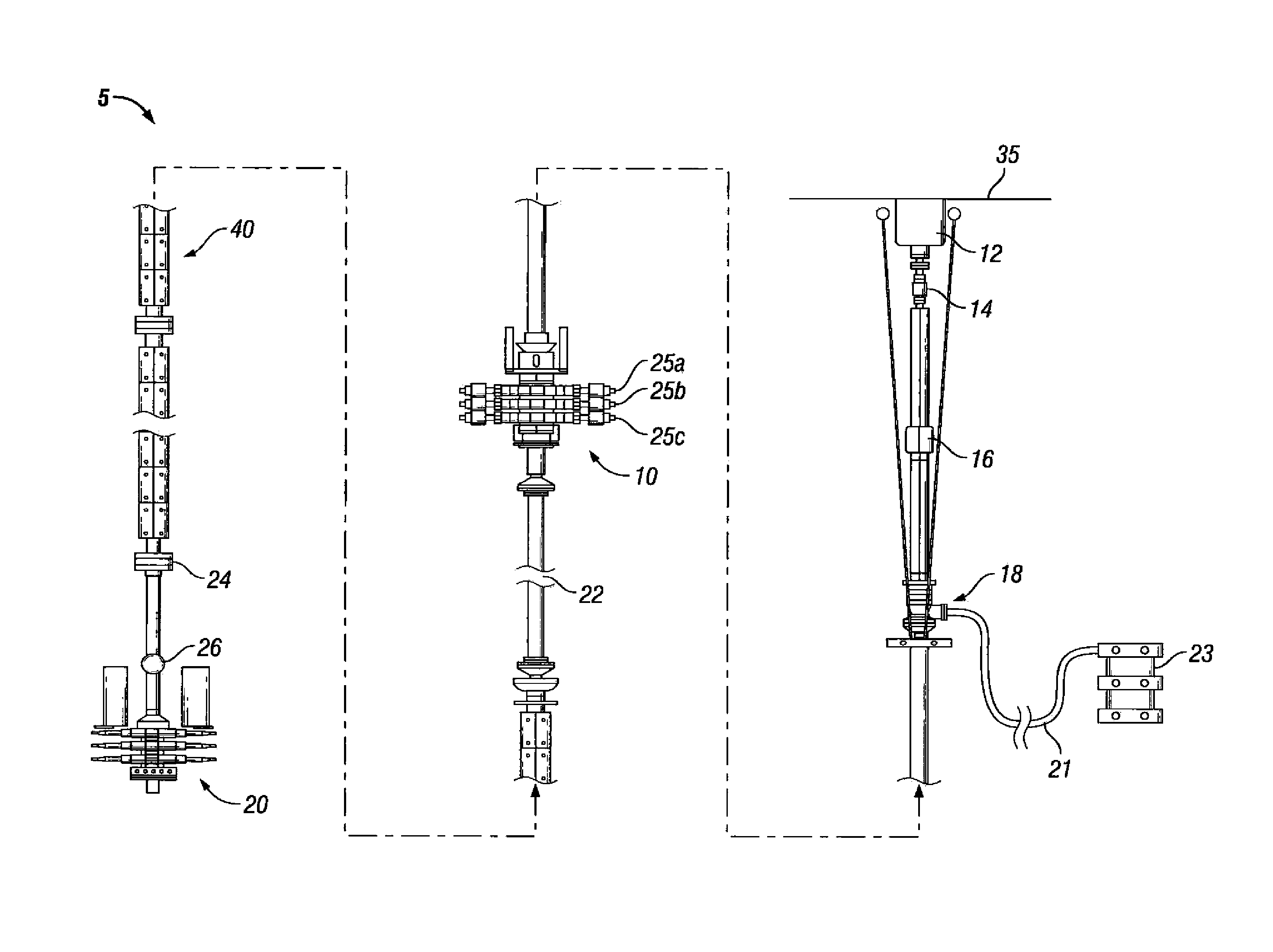
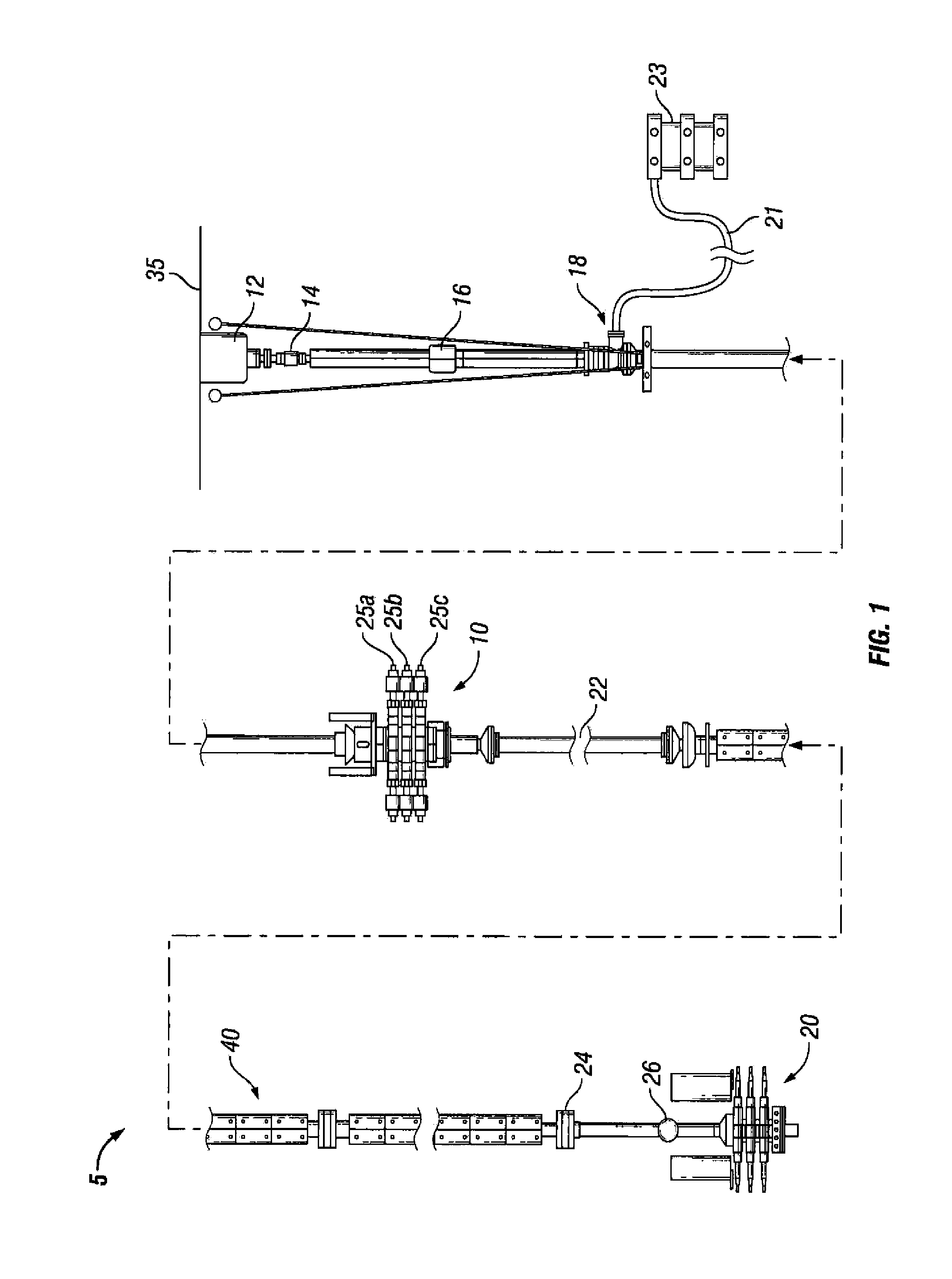
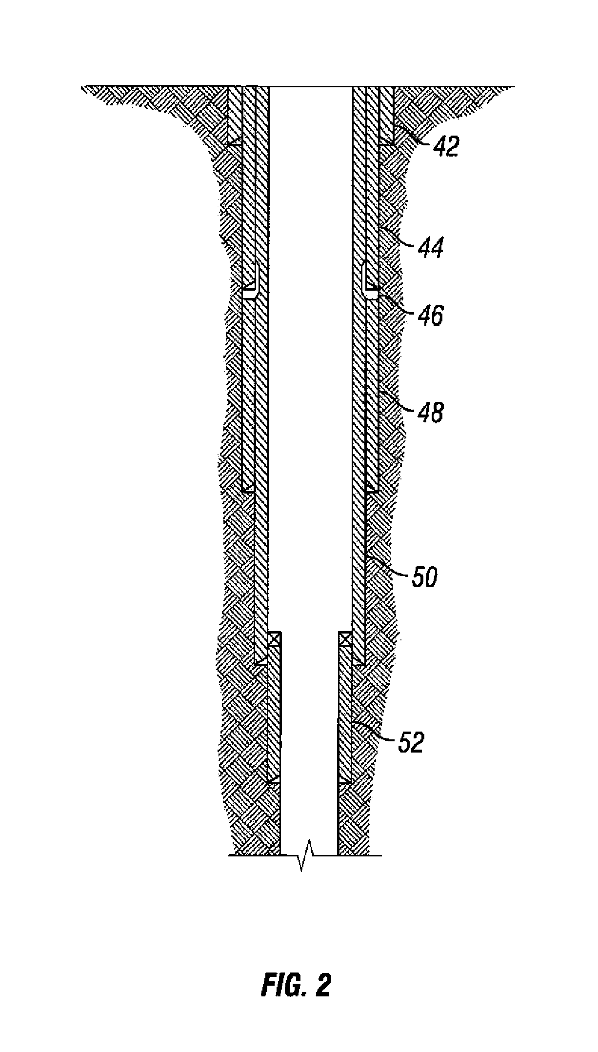
[0011]Illustrative embodiments and methodologies of the invention are described below as they might be employed to allow users to perform advanced drilling and intervention operations in deep water environments. In the interest of clarity, not all features of an actual implementation or methodology are described in this specification. It will of course be appreciated that in the development of any such actual embodiment, numerous implementation-specific decisions must be made to achieve the developers' goals, such as compliance with system-related and business-related constraints, which will vary from one implementation to another. Moreover, it will be appreciated that such a development effort might be complex and time-consuming, but would nevertheless be a routine undertaking for those of ordinary skill in the art having the benefit of this disclosure. Further aspects and advantages of the various embodiments of the invention will become apparent from consideration of the followin...


PUM


Abstract

An assembly suitable for subsea drilling and intervention operations includes a dual blow out preventer system having an upper blow out preventer located between a drill floor and a riser string, and a lower blow out preventer located below the riser string and above a wellhead. The dual BOP system is adapted to enable advanced drilling and intervention operations such as Managed Pressure Drilling (“MPD”), Underbalanced Drilling (“UBD”), or Through Tubing Rotary Drilling (“TTRD”) in an offshore deepwater environment.

Description

PRIORITY[0001]The present application claims the benefit of U.S. Provisional Patent Application Ser. No. 61 / 265,805, entitled “SUBSEA WELL DRILLING AND INTERVENTION METHOD AND APPARATUS,” filed on Dec. 2, 2009, naming Gavin Humphreys as inventor, which is hereby incorporated by reference in its entirety.FIELD OF THE INVENTION[0002]The invention relates to subsea assemblies used in offshore deepwater operations and the production of hydrocarbons.DESCRIPTION OF THE RELATED ART[0003]Hydrocarbon production often requires the placement of drilling equipment in an offshore location. In shallow waters, the rigs and production facilities can be placed on freestanding offshore platforms. As the water becomes deeper, however, use of such platforms becomes impractical. As a result, floating structures, such as drill ships, must be used.[0004]As the desire to drill at greater water depths increases (e.g., to at least 7,500 ft water depth), floatable support structures have become larger due to ...

Claims


Application Information

Patent Timeline
Patent Type & Authority Applications(United States)
IPC IPC(8): E21B7/12
CPCE21B17/017E21B33/038E21B19/004E21B33/035
Inventor HUMPHREYS, GAVIN
Owner STENA DRILLING
Why Eureka
Try Eureka