

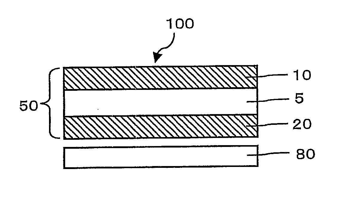
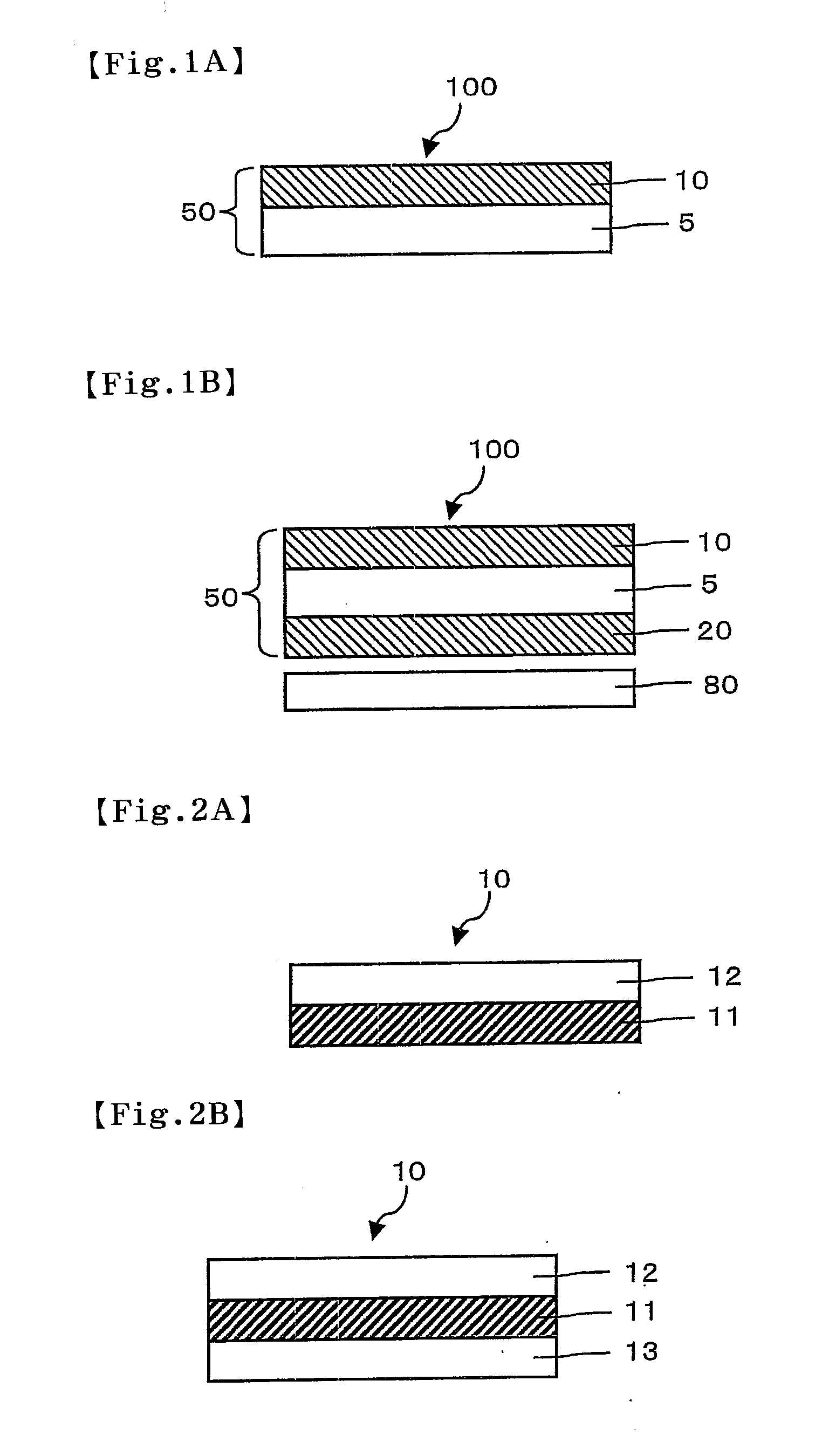
Image display device
a display device and image technology, applied in optics, instruments, electrical equipment, etc., can solve the problems of degrading visibility, high temperature of lcds themselves, and high birefringence of polyester films, so as to improve visibility
- Summary
- Abstract
- Description
- Claims
- Application Information
AI Technical Summary
Benefits of technology
Problems solved by technology
Method used
Image

Examples
example 1
Preparation of Polyester Film
[0120]A 200 μm thick unstretched polyethylene terephthalate film (amorphous) was subjected to free-end uniaxial stretching (longitudinal stretching) in the machine direction for the manufacture of it at a stretch ratio of 2.8 times and then subjected to fixed-end uniaxial stretching (transverse stretching) in the width direction at a stretch ratio of 2.9 times using a tenter stretching machine, so that a crystalline polyester film was obtained. This polyester film was named “protective film A.”
[0121]Formation of Easy-Adhesion Layer on the Polyester Film
[0122]The surface of the protective film A was subjected to a corona treatment. A polyester-based, aqueous dispersion urethane adhesive (SUPERFLEX SF210 (trade name) manufactured by DAI-ICHI KOGYO SEIYAKU CO., LTD.) was then applied to the protective film A using a coating tester equipped with a #200 mesh gravure roll. The coating was dried at 150° C. for 1 minute, so that a 0.3 μm thick easy-adhesion laye...
PUM
 Abstract
Description
Claims
Application Information