Liquid applicator

a liquid applicator and applicator technology, applied in the field of liquid applicators, can solve the problems of easy breakage of the application part, difficult to obtain an appropriate nipping force, and high cost, and achieve the effects of simple structure, simple assembly and robust fixtur

Active Publication Date: 2011-06-02
MITSUBISHI PENCIL CO LTD
View PDF6 Cites 9 Cited by
  • Summary
  • Abstract
  • Description
  • Claims
  • Application Information

AI Technical Summary

Benefits of technology

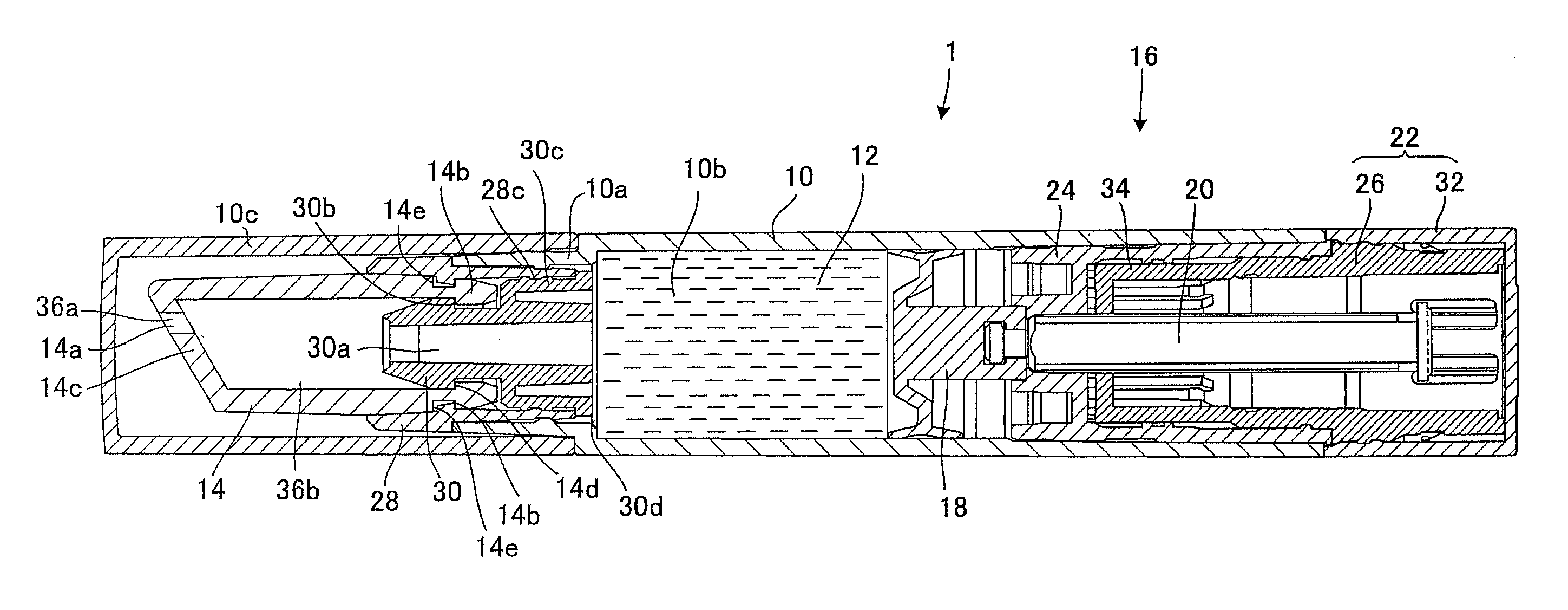
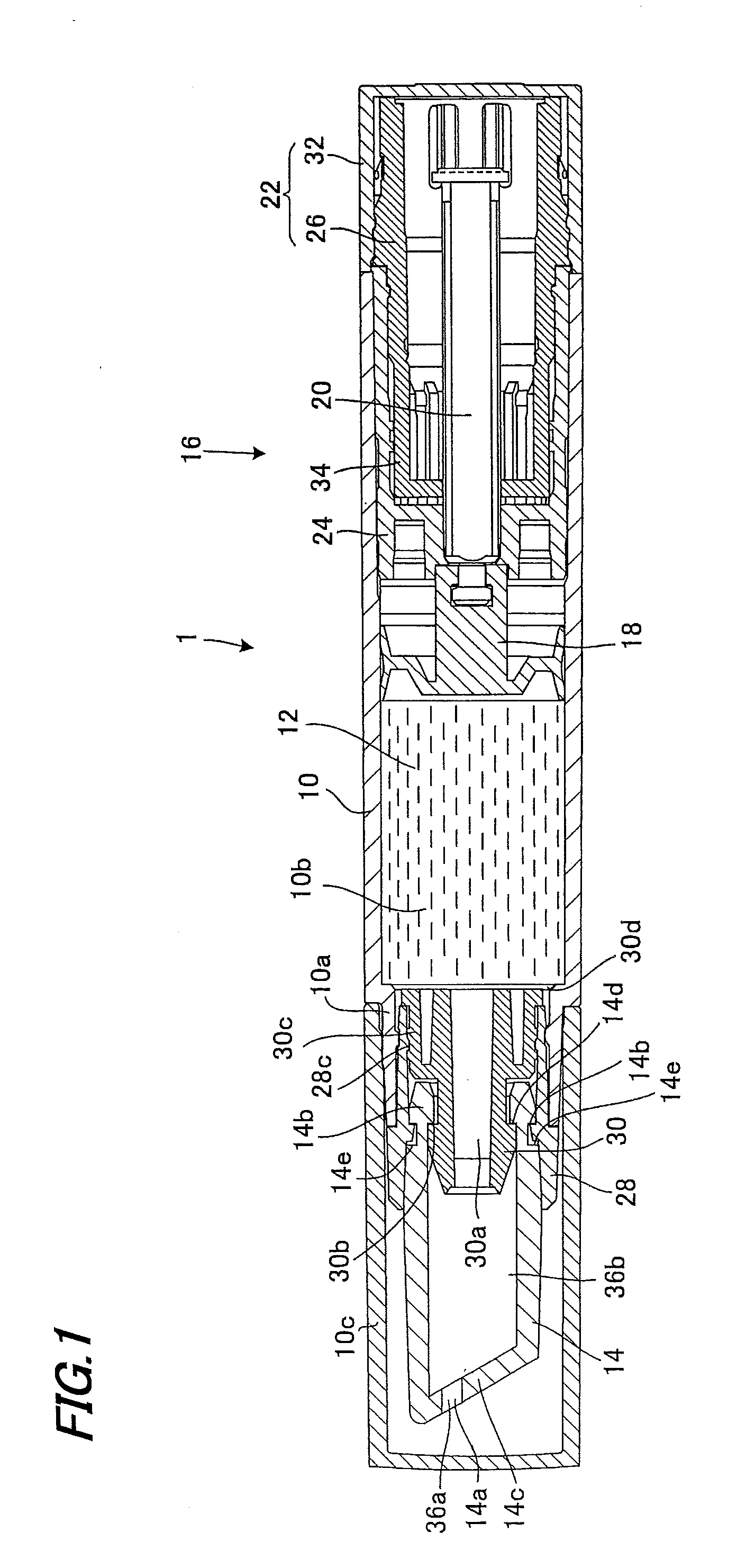
[0029]According to the liquid applicator of the invention defined in Claim 1, in the aforementioned assembled state, the indented / projected engaging portion on the inner peripheral side of the applying part rear end portion is engaged with the indented / projected engaging portion on the outer peripheral side of the joint forward part, at the same time the indented / projected engaging portion on the inner peripheral side of the front barrel rearward part is engaged with the indented / projected engaging portion on the outer peripheral side of the join rearward part, whereby the applying part, joint and front barrel are formed so as to fix the applying part to the barrel body by means of the joint and the front barrel.
[0030]Also, according to the liquid applicator of the invention defined in Claim 2, in the aforementioned assembled state, the indented / projected engaging portion on the inner peripheral side of the applying part rear end portion is engaged with the indented / projected engaging portion on the outer peripheral side of the joint forward part, and the indented / projected engaging portion on the outer peripheral side of the applying part rear end portion is engaged with the indented / projected engaging portion on the inner peripheral side of the front barrel forward part, at the same time the indented / projected engaging portion on the inner peripheral side of the front barrel rearward part is engaged with the indented / projected engaging portion on the outer peripheral side in the join rearward part, whereby the applying part, joint and front barrel are formed so as to fix the applying part to the barrel body by means of the joint and the front barrel.
[0031]Accordingly, according to the invention defined in Claim 1 or 2, it is possible with a simple structure to firmly fix the rear end portion of the applying part from the inside and outside and also produce robust fixture between the joint and the front barrel. As a result, the applying part, front barrel and joint will not come off easily. Further, simple assembling is enabled since the fixture can be created by engagement and fitting between indented / projected engaging portions.
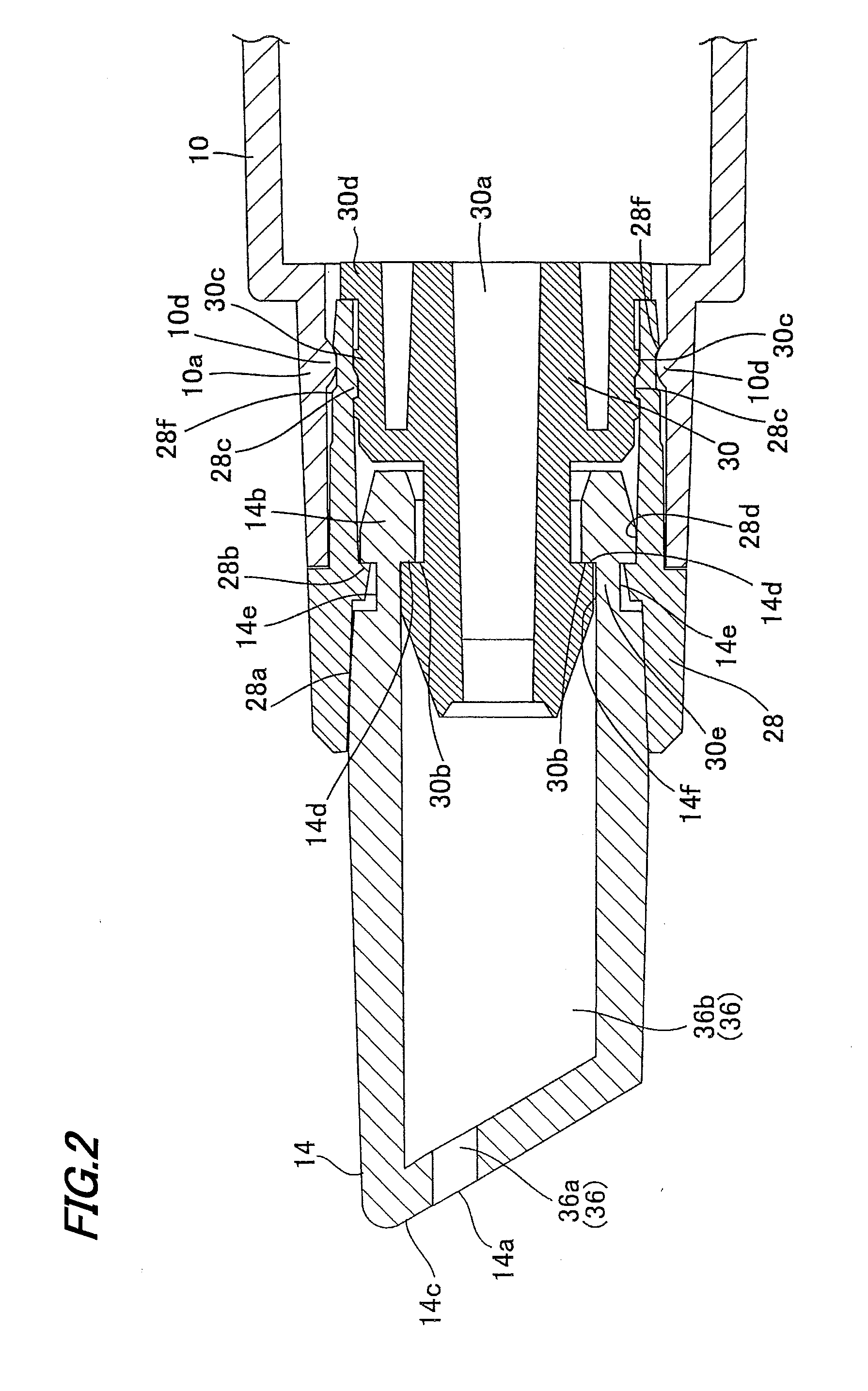
[0032]According to the invention defined in Claim 3, the spacing between the indented / projected engaging portion on the outer peripheral side of the joint forward part and the indented / projected engaging portion on the inner peripheral side of the front barrel forward part is formed to be narrower than the dimension between the indented / projected engaging portions on the inner and outer periphery surfaces of the applying part rear end portion so that the portion between the indented / projected engaging portions on the inner and outer peripheral surfaces of the applying part rear end portion is deformed by exerting compressive stress on that portion. As a result, deformation of the applying part due to compressive stress makes it possible to fix the applying part more firmly.
[0033]Further, according to the invention of Claim 4, in the state where the indented / projected engaging portion on the inner peripheral side of the applying part rear end portion is engaged with the indented / projected engaging portion on the outer peripheral side of the joint forward part and the indented / projected engaging portion on the outer peripheral side of the applying part rear end portion is engaged with the indented / projected engaging portion on the inner peripheral side of the front barrel forward part, the opposing flat surface portions on the applying part inner periphery and the joint outer periphery are formed so as to come into close contact with each other while the opposing surface portions on the applying part outer periphery and the front barrel inner periphery are formed so as to come into close contact with each other. As a result, the flat surfaces of the applying part's inner periphery and the joint's outer periphery are put into close contact with each other and the flat surfaces of the applying part's outer periphery and the front barrel's inner periphery are put into close contact with each other to thereby improve liquid-tightness and make it difficult to be distorted and hence coming off.
[0034]According to the invention of Claim 5, in the state where the indented / projected engaging portion on the inner peripheral side of the applying part rear end portion is engaged with the indented / projected engaging portion on the outer peripheral side of the joint forward part and the indented / projected engaging portion on the outer peripheral side of the applying part rear end portion is engaged with the indented / projected engaging portion on the inner peripheral side of the front barrel forward part, the flange portion is adapted to abut the rear end of the front barrel from behind. As a result, it is possible to prevent the joint from sinking into the front barrel.

Problems solved by technology

However, the attachment structure of Patent Document 1 not only needs a technique of a high order in order to integrally form the inner annular seat and outer annular seat, facing difficulties in forming and resulting in high cost, but it is also difficult to obtain an appropriate nipping force for nipping the body of the applying part so that the seats and / or the applying part are prone to be broken during use, causing trouble.
However, since in this technique, engagement is created by only one undercut of the inner sleeve, it is not the one that can produce high enough fixing force.
Accordingly, the conventional liquid applicators entail the fear, for example that the applying part comes off due to a wiping operation of wiping up the soil of the liquid around the applying part, the liquid leaks out, smudging garments, and also the fear that the applying part cannot be re-attached even if it is tried to.

Method used


Image

  • Liquid applicator
  • Liquid applicator
  • Liquid applicator

Examples


embodiment 1

[0103]Average; 22.6 (N), Maximum 25 (N), Minimum 20 (N)

embodiment 2

[0104]Average; 52.3 (N), Maximum 56 (N), Minimum 50 (N)

[0105]As shown above, in embodiment 1, the average is 22.6 (N), which gives a pull-out resistance value free from problems for practical use. In embodiment 2, the value of pull-out is about twice as high as the value in embodiment 1, which means that the applying part is fixed more firmly compared to embodiment 1. Accordingly, it is understood that the liquid applicator of embodiment 2 is suitable for use in applying high-viscosity application liquids and for applying a liquid on a high-friction target surface.

[0106]Next, embodiment 3 will be described.

[0107]FIGS. 7 to 8 are illustrative views showing embodiment 3 of a liquid applicator according to the present invention.

[0108]As shown in FIGS. 7 to 8, in the liquid applicator according to embodiment 3, a joint 30 is an overall hollow cylindrical body having an application liquid passage hole 30a formed therein and indented / projected engaging portions 30b and 30c formed on the o...


PUM


Abstract

The present invention is a liquid applicator which, in its assembled state an applying part, joint, and front barrel are fixed to a barrel body front end portion, the step of an indented/projected engaging portion on the inner peripheral side of the applying part rear end portion is abutted from behind against and engaged with the step of an indented/projected engaging portion on the outer peripheral side of the forward part of the joint. At the same time, an indented/projected engaging portion on the outer peripheral side of the applying part rear end portion is abutted against and engaged with an indented/projected engaging portion on the inner peripheral side of the front barrel's forward part, and an indented/projected engaging portion on the inner peripheral side of the front barrel rearward part is engaged with an indented/projected engaging portion on the outer peripheral side in the rearward part of joint, whereby applying part, joint and front barrel are formed so as to fix the applying part to barrel body by means of the joint and the front barrel.

Description

TECHNICAL FIELD[0001]The present invention relates to a liquid applicator that stores an application liquid such as a fluid cosmetic or the like in a reservoir arranged in a barrel, has an applying part arranged at the front end of the barrel and made of a soft elastic body that is put into contact with a target site, and pushes out the application liquid stored in the reservoir by means of a delivering mechanism located at the end part of the barrel, wherein the applying part capable of applying the application liquid to a target site such as a skin as it is being slid over the target site is disposed in the barrel so as not to fall off.BACKGROUND ART[0002]In general, an applicator (liquid applicator) for applying a liquid cosmetic etc., with an applying part is adapted to push the application liquid from a reservoir arranged in the barrel to the ejection port of the soft applying part arranged at the barrel tip so as to be able to apply the application liquid to a target site as t...

Claims


Application Information

Patent Timeline
Patent Type & Authority Applications(United States)
IPC IPC(8): A45D34/04
CPCA45D34/04B05C17/0133A45D40/26
Inventor UEHARA, JUNYA
Owner MITSUBISHI PENCIL CO LTD
Why Eureka
Try Eureka