
Gtl-fpso system for conversion of associated gas in oil fields and stranded gas in stranded gas fields, and process for production of synthetic fuel using the same

a technology of stranded gas and associated gas, which is applied in the direction of oxygen-containing compound preparation, sustainable manufacturing/processing, petrochemical industry, etc., can solve the problems of catalyst deactivation and high investment cost of oxygen plant facilities, and achieve the effect of improving the production yield of liquid hydrocarbons

Active Publication Date: 2011-06-02
KOREA INST OF SCI & TECH
View PDF14 Cites 29 Cited by
  • Summary
  • Abstract
  • Description
  • Claims
  • Application Information

AI Technical Summary

Benefits of technology

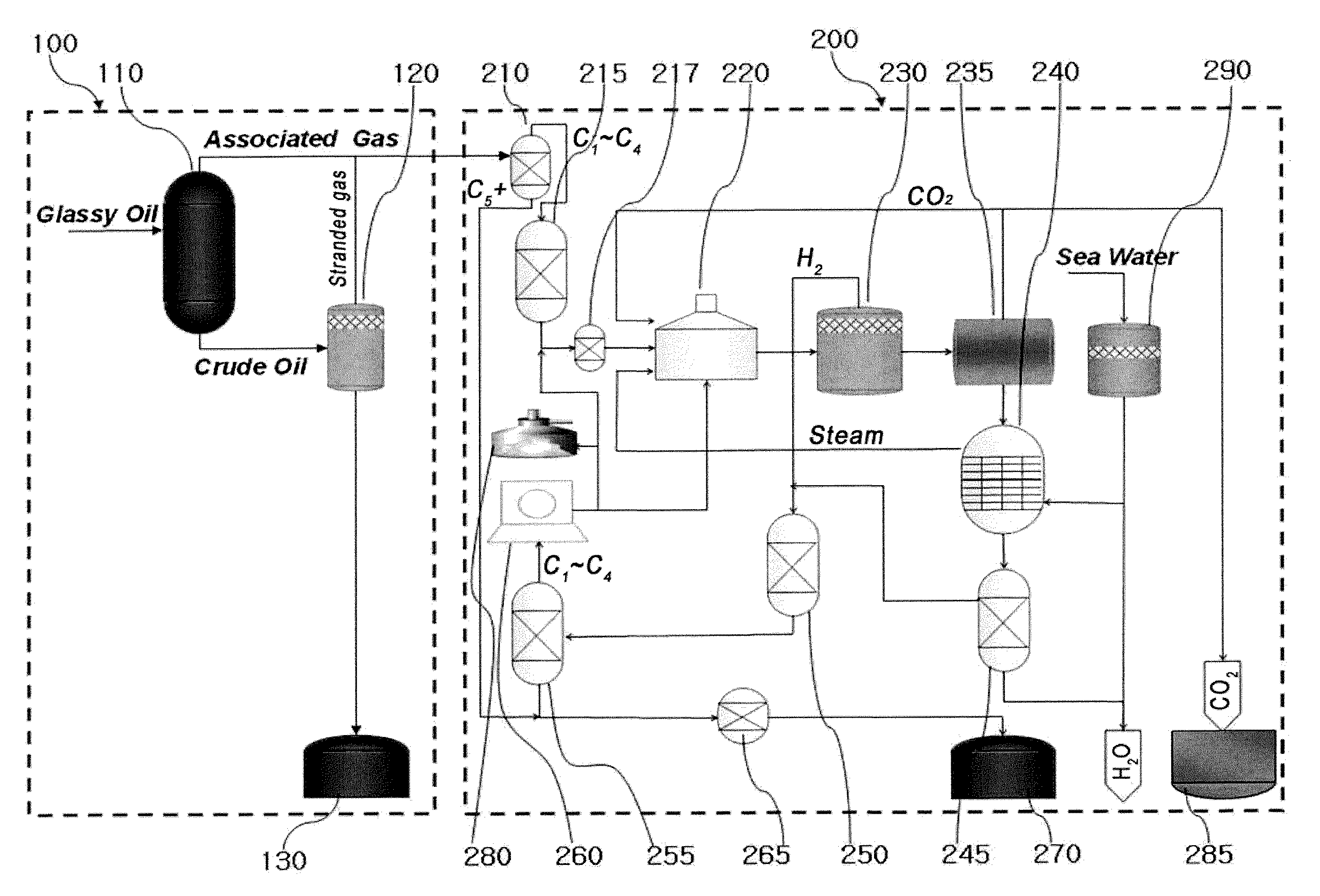
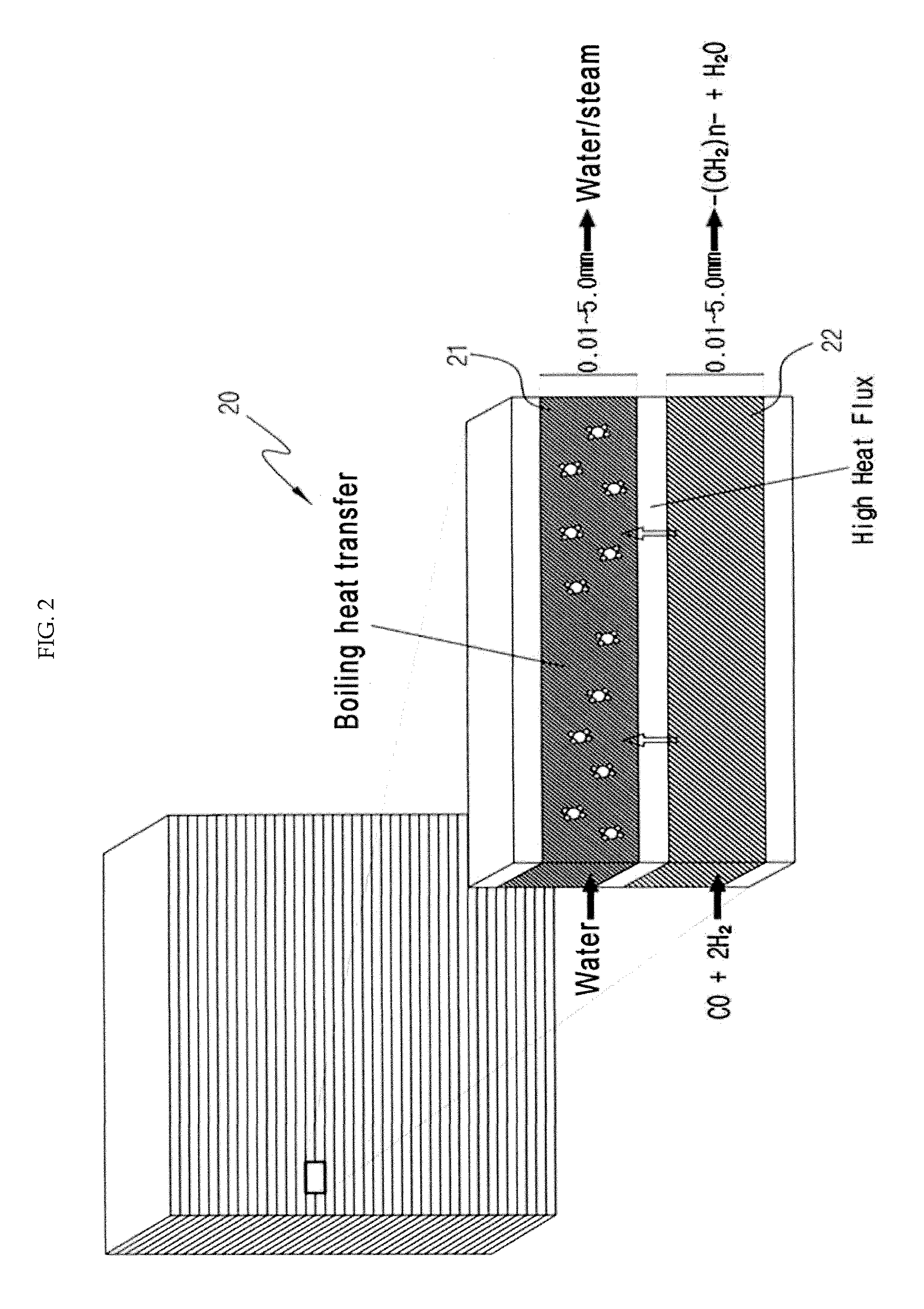
[0041]When the liquid hydrocarbon is produced by the Fischer-Tropsch reaction, a process of adjusting the composition of the synthetic gas required depending on the reforming or the particular catalyst system by the water-gas shift reaction or the reverse water-gas shift reaction may be included. Through this, the production yield of the liquid hydrocarbon may be improved.

Problems solved by technology

However, since the existing GTL process is inappropriate for medium-to-small sized stranded gas fields (0.1 to 5 Tcf: trillion cubic feet), which account for the majority of gas reserves, when considering investment costs, there is a need for an offshore compact GTL process for converting natural gas produced from medium-to-small sized stranded gas fields to a liquid fuel.
Because oxygen is needed for the process, investment cost for the oxygen plant facility is high.
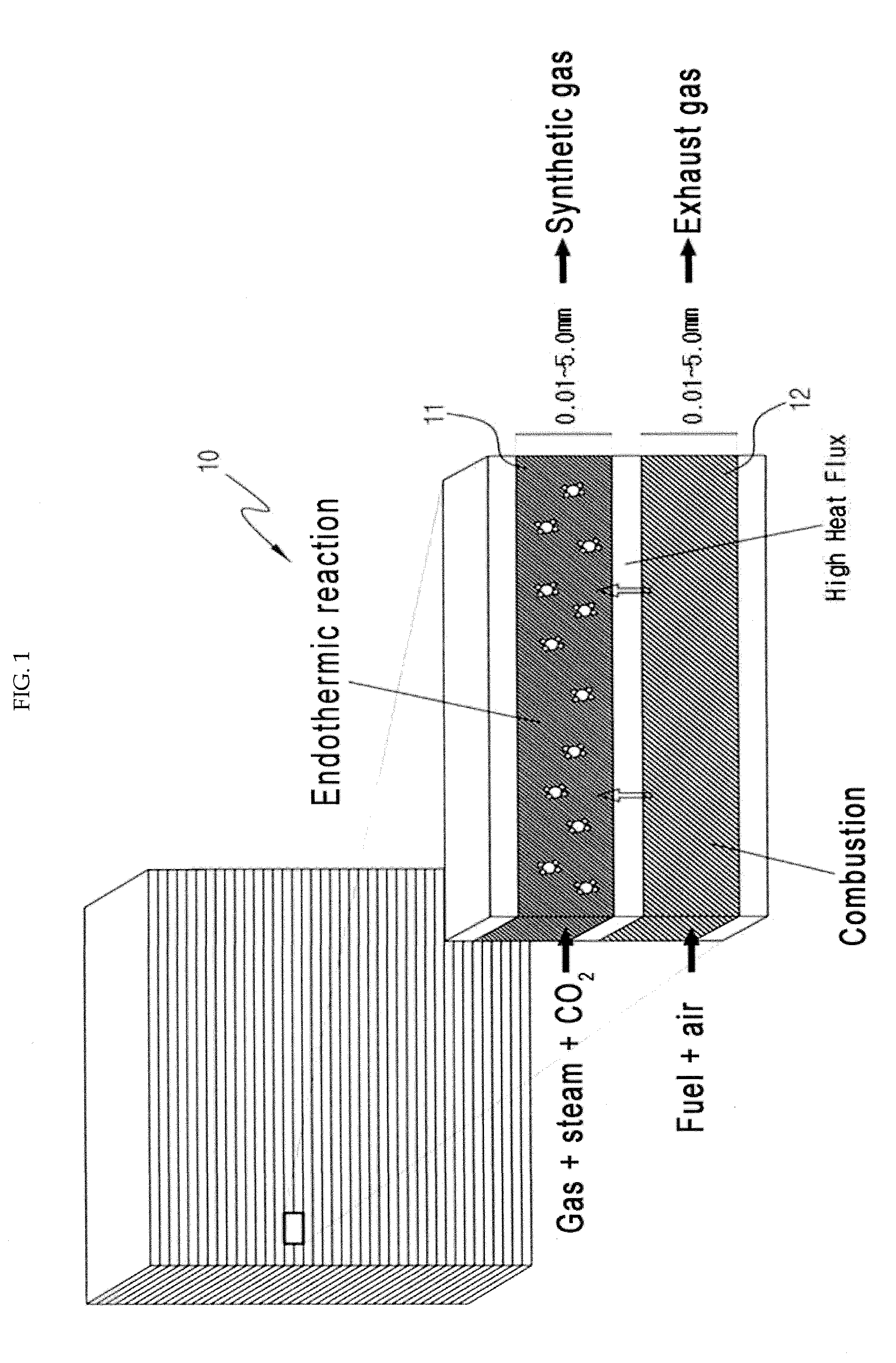
Further, unwanted side reactions including conversion of the synthetic gas to methane [methanation; reaction formula (6)], water-gas shift reaction [reaction formula (7)] and coking which results in deactivation of the catalyst [Boudouard reaction, reaction formula (8)] may occur.

Method used


Image

  • Gtl-fpso system for conversion of associated gas in oil fields and stranded gas in stranded gas fields, and process for production of synthetic fuel using the same
  • Gtl-fpso system for conversion of associated gas in oil fields and stranded gas in stranded gas fields, and process for production of synthetic fuel using the same
  • Gtl-fpso system for conversion of associated gas in oil fields and stranded gas in stranded gas fields, and process for production of synthetic fuel using the same

Examples


Embodiment Construction

[0052]Hereinafter, reference will now be made in detail to various embodiments of the present disclosure, examples of which are illustrated in the accompanying drawings and described below. While the disclosure will be described in conjunction with exemplary embodiments, it will be understood that the present description is not intended to limit the disclosure to those exemplary embodiments. On the contrary, the disclosure is intended to cover not only the exemplary embodiments, but also various alternatives, modifications, equivalents and other embodiments, which may be included within the spirit and scope of the disclosure as defined by the appended claims.

[0053]The present disclosure relates to a gas to liquids (GTL)-floating production, storage and offloading (FPSO) system producing synthetic fuel from gas or glassy oil extracted from stranded gas fields or offshore oil fields using a reforming reactor, a liquid hydrocarbon producer, or the like, and a method for producing the s...


PUM

PropertyMeasurementUnit
compositionaaaaaaaaaa
temperatureaaaaaaaaaa
pressureaaaaaaaaaa

Abstract

Disclosed are a gas to liquids (GTL)-floating production, storage and offloading (FPSO) system that can be used in offshore oil fields or stranded gas fields and a method for producing synthetic fuel using the same. More particularly, the disclosure relates to a GTL-FPSO system capable of producing liquid synthetic fuel from gas extracted from stranded gas fields or associated gas extracted from oil fields, including a reforming reactor and a liquid hydrocarbon producer, and a method for producing the same.

Description

CROSS-REFERENCE TO RELATED APPLICATIONS[0001]This application claims priority under 35 U.S.C. §119 to Korean Patent Application No. 10-2009-0116000, filed on Nov. 27, 2009, in the Korean Intellectual Property Office, the disclosure of which is incorporated herein by reference in its entirety.BACKGROUND[0002](a) Technical Field[0003]The present disclosure relates to a gas to liquids (hereinafter GTL)-floating production, storage and offloading (hereinafter FPSO) system that can be used in offshore oil fields or stranded gas fields and a method for producing synthetic fuel using the same. More particularly, the disclosure relates to a GTL-FPSO system capable of producing liquid synthetic fuel from gas extracted from stranded gas fields or associated gas extracted from oil fields, including a reforming reactor and a liquid hydrocarbon producer, and a method for producing the same.[0004](b) Background Art[0005]With the recent rapid increase in oil prices, there has been a growing concer...

Claims


Application Information

Patent Timeline
Patent Type & Authority Applications(United States)
IPC IPC(8): C07C1/04B01J19/00
CPCB01J19/0093B01J2219/00783B01J2219/00835B01J2219/00873C07C1/12C10G2/32C10G2300/4062C10G2300/4068C10G2300/1033C07C1/0485C01B2203/066B01J8/00C01B2203/86C01B2203/062C01B2203/0227C01B2203/061Y02P20/10Y02P30/00Y02E60/50B63B35/44C10G5/00H01M8/04
Inventor MOON, DONG JULEE, YUN JUKANG, JUNG SHIKPARK, MOONJUKIM, SOJUNGLEE, SANG DEUKLEE, HYUNJOO
Owner KOREA INST OF SCI & TECH
Learn More