Catalyst degradation determination device for exhaust purification system

a technology of degradation determination and exhaust purification system, which is applied in the direction of mechanical equipment, machines/engines, electric control of exhaust treatment, etc., can solve the problems of affecting the purification performance of exhaust, the accuracy of degradation determination by this device is considerably low, and the ammonia cannot be generated by hydrolysis, etc., to achieve the effect of suppressing a temporary decline in purification performan

Inactive Publication Date: 2011-06-09
HONDA MOTOR CO LTD
View PDF6 Cites 22 Cited by
  • Summary
  • Abstract
  • Description
  • Claims
  • Application Information

AI Technical Summary

Benefits of technology

[0038]According to this invention, NOx in exhaust can be reliably purified even while determining the degradation, by fluctuating the storage amount in a selective reduction catalyst that is in a state in which the storage amount is a maxi

Problems solved by technology

However, with the device of Patent Document 2, the storage amount of the selective reduction catalyst when initiating the supply of urea water for degradation determination is indefinite, and thus becomes a parameter that differs each time performing degradation determination.
If the initial storage amount changes, the time from initiating the supply of urea water until ammonia slip occurs will also change, and thus the degradation determination precision by this device is considerably low.
In addition, although urea water is intended to be supplied in a low temperature region such th

Method used


Image

  • Catalyst degradation determination device for exhaust purification system
  • Catalyst degradation determination device for exhaust purification system
  • Catalyst degradation determination device for exhaust purification system

Examples


Embodiment Construction

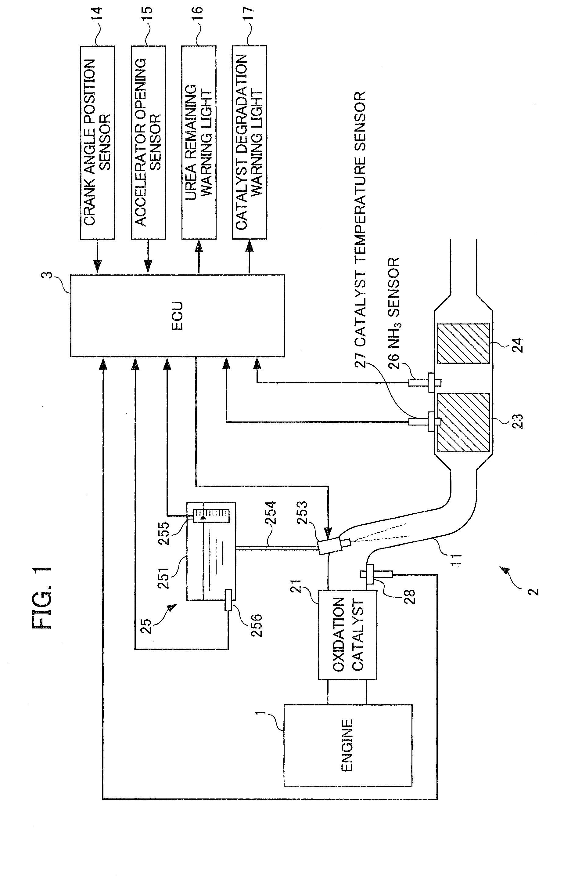
[0062]One embodiment of the present invention will be explained hereinafter while referring to the drawings. FIG. 1 is a schematic diagram showing configurations of an exhaust purification system 2 of an internal combustion engine (hereinafter referred to as “engine”) 1 and a catalyst degradation determination device thereof according to the embodiment of the present invention. The engine 1 is a gasoline engine of lean-burn operating type or a diesel engine, and is mounted in a vehicle, which is not illustrated.

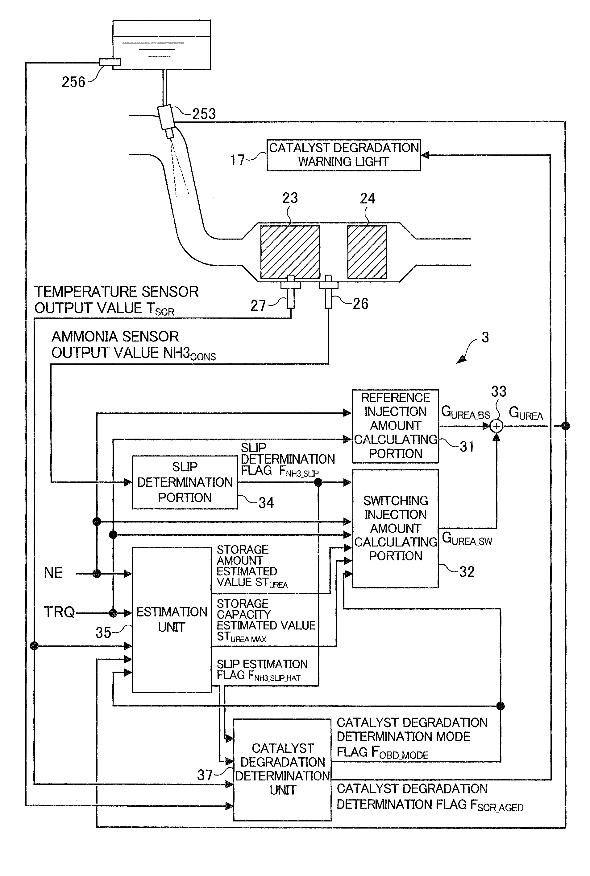
[0063]The exhaust purification system 2 is configured to contain a selective reduction catalyst 23 that is provided in an exhaust channel 11 of the engine 1 and purifies nitrogen oxides (hereinafter referred to as “NOx”) in exhaust flowing through this exhaust channel 11 under the presence of ammonia as a reducing agent, a urea injection device 25 that supplies urea water, which is a source of the reducing agent, into the exhaust channel 11 on an upstream side of the selectiv...


PUM


Abstract

A catalyst degradation determination device is provided that can determine the degradation of a selective reduction catalyst with high precision while also suppressing a temporary decline in purification performance. By way of controlling a urea injection device, the catalyst degradation determination device increases, in a selective reduction catalyst in a state in which the storage amount is a maximum, the storage amount thereof by a detection reduced-amount portion DSTNH3<sub2>—</sub2>JD and then decreases the amount until it is determined that ammonia slip has occurred. Then, degradation is determined based on the time at which the slip determination flag FNH3<sub2>—</sub2>SLIP was set to “1” when fluctuating the storage amount. The detection reduced-amount portion DSTNH3<sub2>—</sub2>JD is set to a value that is larger than the storage capacity of the selective reduction catalyst in a degraded state and smaller than the storage capacity of the selective reduction catalyst in a normal state.

Description

[0001]This application is based on and claims the benefit of priority from Japanese Patent Application No. 2009-279654, filed on 9 Dec. 2009, the content of which is incorporated herein by reference.BACKGROUND OF THE INVENTION[0002]1. Field of the Invention[0003]The present invention relates to a catalyst degradation determination device for an exhaust purification system. In particular, it relates to a catalyst degradation determination device for an exhaust purification system equipped a selective reduction catalyst that reduces NOx in exhaust under the presence of a reducing agent.[0004]2. Related Art[0005]Conventionally, as one exhaust purification system that purifies NOx in exhaust, a system has been proposed in which a selective reduction catalyst that selectively reduces NOx in the exhaust by way of a reducing agent is provided in an exhaust channel. For example, with an exhaust purification system of urea addition type, urea water is supplied from an upstream side of the se...

Claims


Application Information

Patent Timeline
IPC IPC(8): F01N11/00
CPCF01N3/206Y02T10/24F01N11/00F01N2550/02F01N2550/03F01N2550/05F01N2560/021F01N2560/026F01N2570/14F01N2610/02F01N2610/1473F01N2900/1402F01N2900/1622Y02T10/47F01N3/2066Y02T10/12Y02T10/40
Inventor YASUI, YUJIHASHIMOTO, EIJI
Owner HONDA MOTOR CO LTD
Why Eureka
Try Eureka