Refractive index distribution measuring method and refractive index distribution measuring apparatus

a technology of refractive index and measuring method, which is applied in the direction of instruments, optical apparatus testing, structural/machine measurement, etc., can solve the problems of deteriorating measurement accuracy and inability to obtain desired optical characteristics, and achieve the effect of high-precision measurement of internal refractive index distribution

Inactive Publication Date: 2011-06-09
CANON KK
View PDF20 Cites 37 Cited by
  • Summary
  • Abstract
  • Description
  • Claims
  • Application Information

AI Technical Summary

Benefits of technology

[0011]The present invention provides a method and an apparatus capable of highly accurately measuring an internal refractive index distribution of a high refractive index object even when soaking the object in a low refractive index medium.

Problems solved by technology

Such internal refractive index nonuniformity greatly affects optical characteristics of the optical element, which may make it impossible to obtain desired optical characteristics.
This method enables measurement of an internal refractive index distribution of the object without accurate processing of the object.
Therefore, when measuring a transmitted wavefront of an object whose refractive index is high by the measuring methods disclosed in Japanese Patent Laid-Open Nos. 01-316627 and 02-008726, the detector outputs only a small signal, which deteriorates measurement accuracy.

Method used


Image

  • Refractive index distribution measuring method and refractive index distribution measuring apparatus
  • Refractive index distribution measuring method and refractive index distribution measuring apparatus
  • Refractive index distribution measuring method and refractive index distribution measuring apparatus

Examples


embodiment 1

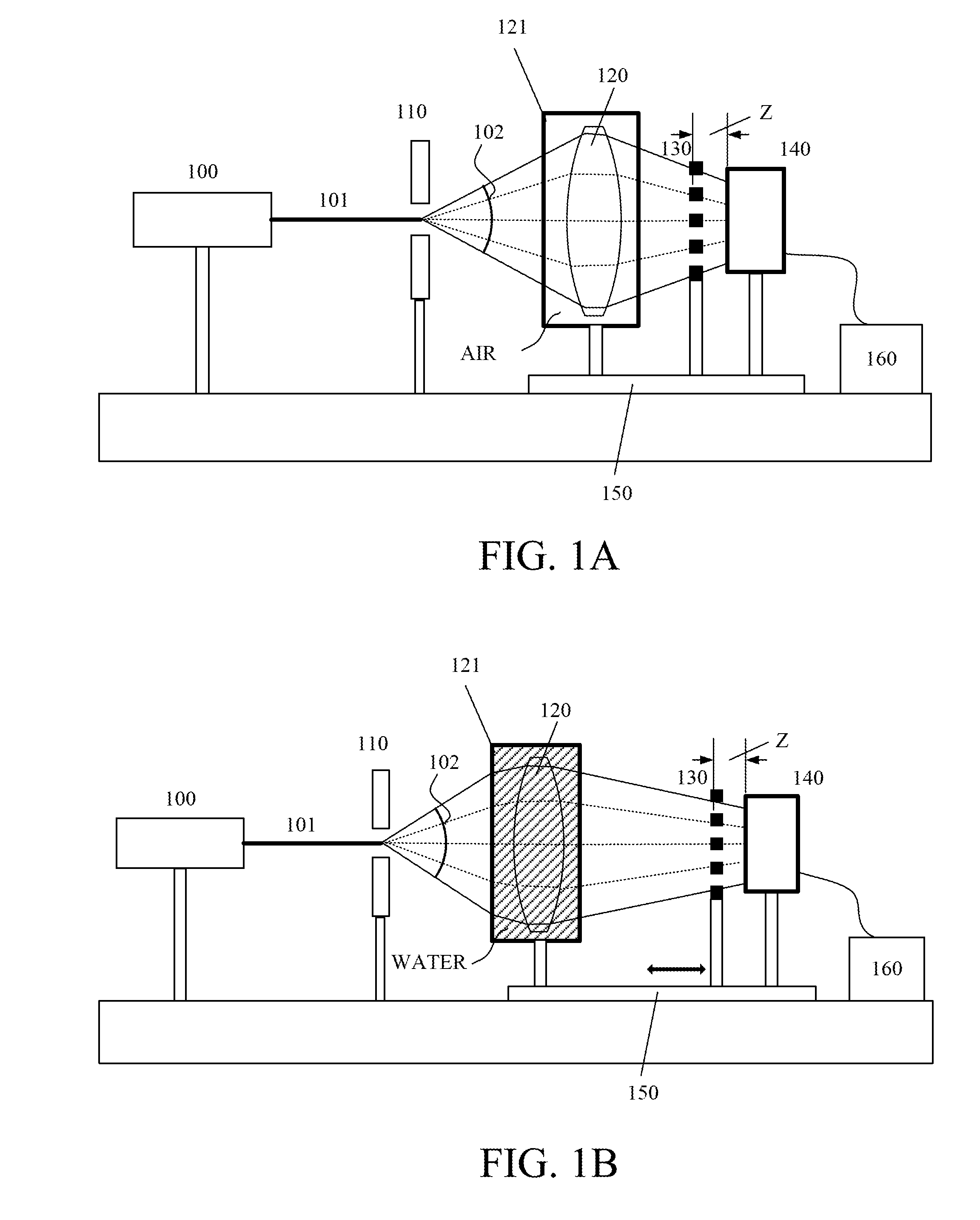
[0025]In a first embodiment (Embodiment 1) of the present invention, description will be made of a refractive index distribution measuring method that measures transmitted wavefronts of an object being soaked in two media (air and water, for example) to calculate an internal refractive index distribution of the object.

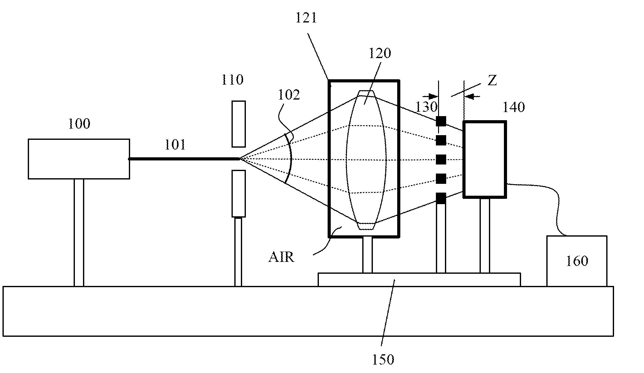
[0026]FIG. 1A shows a configuration of a Talbot interferometer (refractive index measuring apparatus) that soaks an object 120 which is an optical element such as a lens in air (first medium) to measure a transmitted wavefront (first transmitted wavefront) of the object 120. The object 120 is placed inside an object case 121 and soaked in the air. A refractive index (first refractive index) of the air is lower than that of the object 120 by 0.01 or more.

[0027]Laser light emitted from a laser light source (for example, a He—Ne laser light source) 100 passes through a pinhole (optical member) 110 to be diffracted thereat. The laser light, that is, the diffracted light th...

embodiment 2

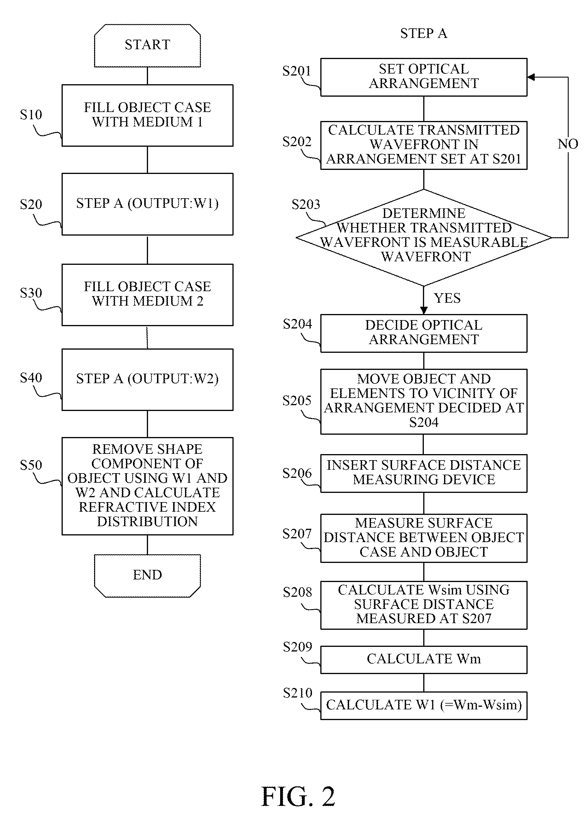
[0069]A second embodiment (Embodiment 2) of the present invention will describe a case of simultaneously measuring a refractive index of a medium to reflect it into calculation of the refractive index distribution of the object. A flowchart of FIG. 5 shows a procedure for calculating the refractive index distribution in this embodiment. This embodiment will describe differences from the procedure in Embodiment 1 (FIG. 2). The procedure shown in FIG. 5 is different in steps T10 and T305 to T311 from that shown in FIG. 2.

[0070]In this embodiment, the procedure first measures a thickness (central thickness) D of a center of the object 120 or a central refractive index Nglass that is a refractive index averaged in a thickness direction at the center of the object (step T10).

[0071]Thereafter, at steps T20 to T60, the procedure performs step B to calculate a wavefront aberration W1 in a case where a medium in the object case 121 is air (first medium, MEDIUM 1) and a wavefront aberration W...

embodiment 3

[0081]A third embodiment (Embodiment 3) of the present invention will describe a case where an object 120 has a negative optical power (an optical power is an inverse of a focal length) and a refractive index measuring apparatus other than the shearing interferometer is used. FIG. 6 schematically shows a configuration of the refractive index measuring apparatus of this embodiment.

[0082]A pinhole 110 generates light (reference light) having an ideal spherical wave using laser light emitted from a laser light source 100. The light is converted into convergent light by an illumination system 600. The convergent light passes through the object 120 that is a meniscus lens, and a transmitted wavefront thereof is measured by a Shack-Hartmann sensor 610 that is a wavefront measuring sensor. The Shack-Hartmann sensor 610 is constituted by a lens array 611 and a CCD 612 as shown in FIG. 7.

[0083]Moving the object 120 in an optical axis direction along a rail 150 enables a light flux entering t...


PUM

PropertyMeasurementUnit
refractive indexaaaaaaaaaa
diameteraaaaaaaaaa
diameteraaaaaaaaaa

Abstract

The measuring method includes a step of causing reference light to enter an object placed in a first medium to measure a first transmitted wavefront, a step of causing the reference light to enter the object placed in a second medium to measure a second transmitted wavefront, a step of measuring first and second placement positions where the object is placed in the first and second media, and a calculating step of calculating an internal refractive index distribution of the object by using measurement results of the first and second transmitted wavefronts. The calculating step calculates the internal refractive index distribution from which a shape component of the object is removed by using the measurement results of the first and second transmitted wavefronts, and first and second reference transmitted wavefronts of a reference object to be placed at positions identical to the first and second placement positions.

Description

BACKGROUND OF THE INVENTION[0001]1. Field of the Invention[0002]The present invention relates to a method and an apparatus for measuring a refractive index distribution of an object such as an optical element.[0003]2. Description of the Related Art[0004]Optical elements such as lenses that are used for optical apparatuses such as digital cameras and laser beam printers require high refractive indices. On the other hand, molding technology enables easy production of complex shapes such as aspheric surfaces even when using optical glasses and plastics having high refractive indices.[0005]However, the molding sometimes causes, inside the optical element, refractive index nonuniformity depending on molding conditions. Such internal refractive index nonuniformity greatly affects optical characteristics of the optical element, which may make it impossible to obtain desired optical characteristics. Therefore, highly accurate measurement of internal optical homogeneity of the optical elemen...

Claims


Application Information

Patent Timeline
Patent Type & Authority Applications(United States)
IPC IPC(8): G01N21/41
CPCG01M11/0228G01N21/41G01M11/0264G01M11/025
Inventor KATO, SEIMA
Owner CANON KK
Why Eureka
Try Eureka