

Laser projector
a laser projector and projector technology, applied in projectors, color television details, instruments, etc., can solve the problems loss of light, and difficulty in keeping the projector for a long time, so as to reduce the degree of oblique projection onto the projection surface, reduce trapezoidal distortion, and reduce the effect of trapezoidal distortion
- Summary
- Abstract
- Description
- Claims
- Application Information
AI Technical Summary
Benefits of technology
Problems solved by technology
Method used
Image

Examples
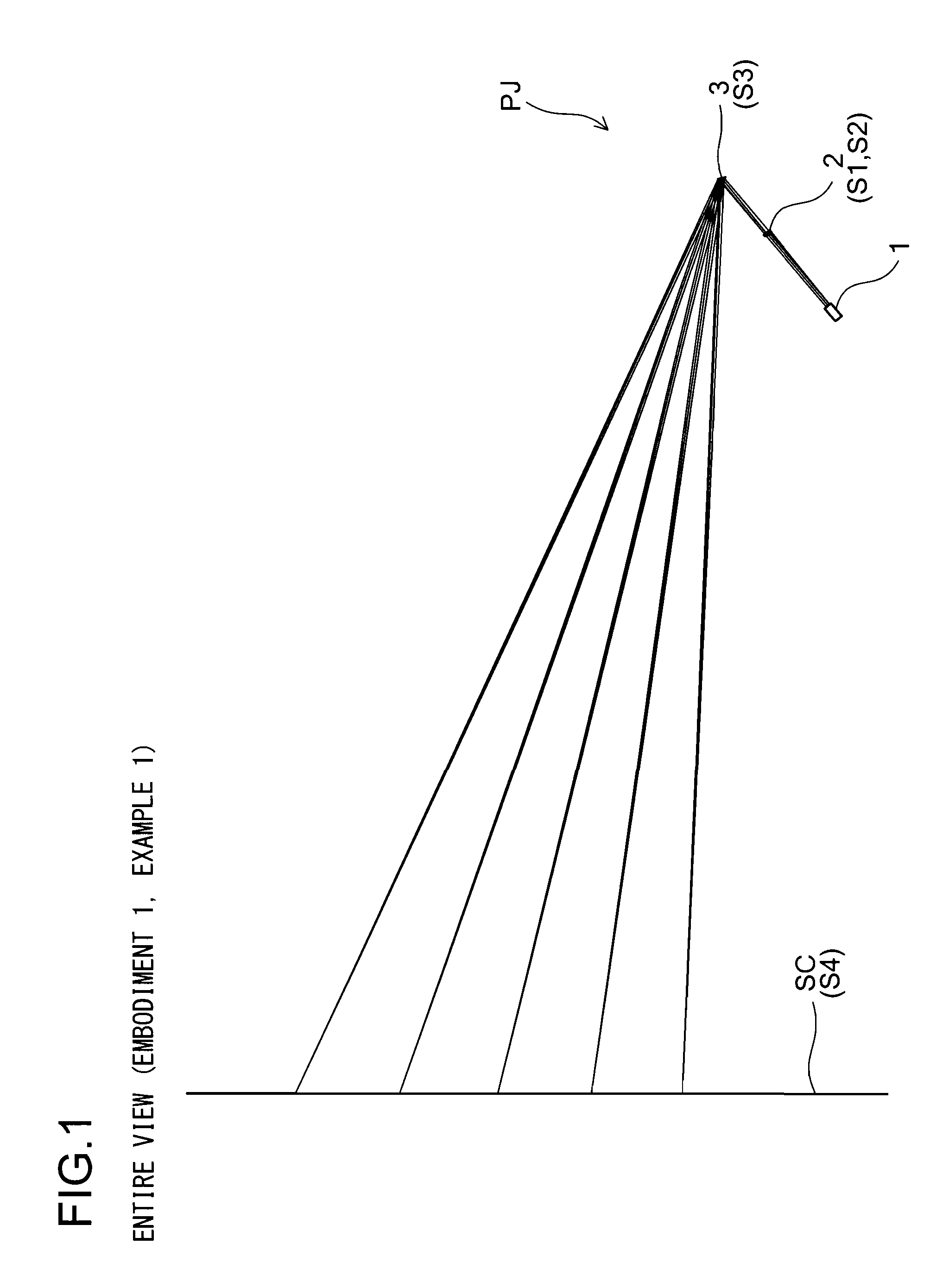
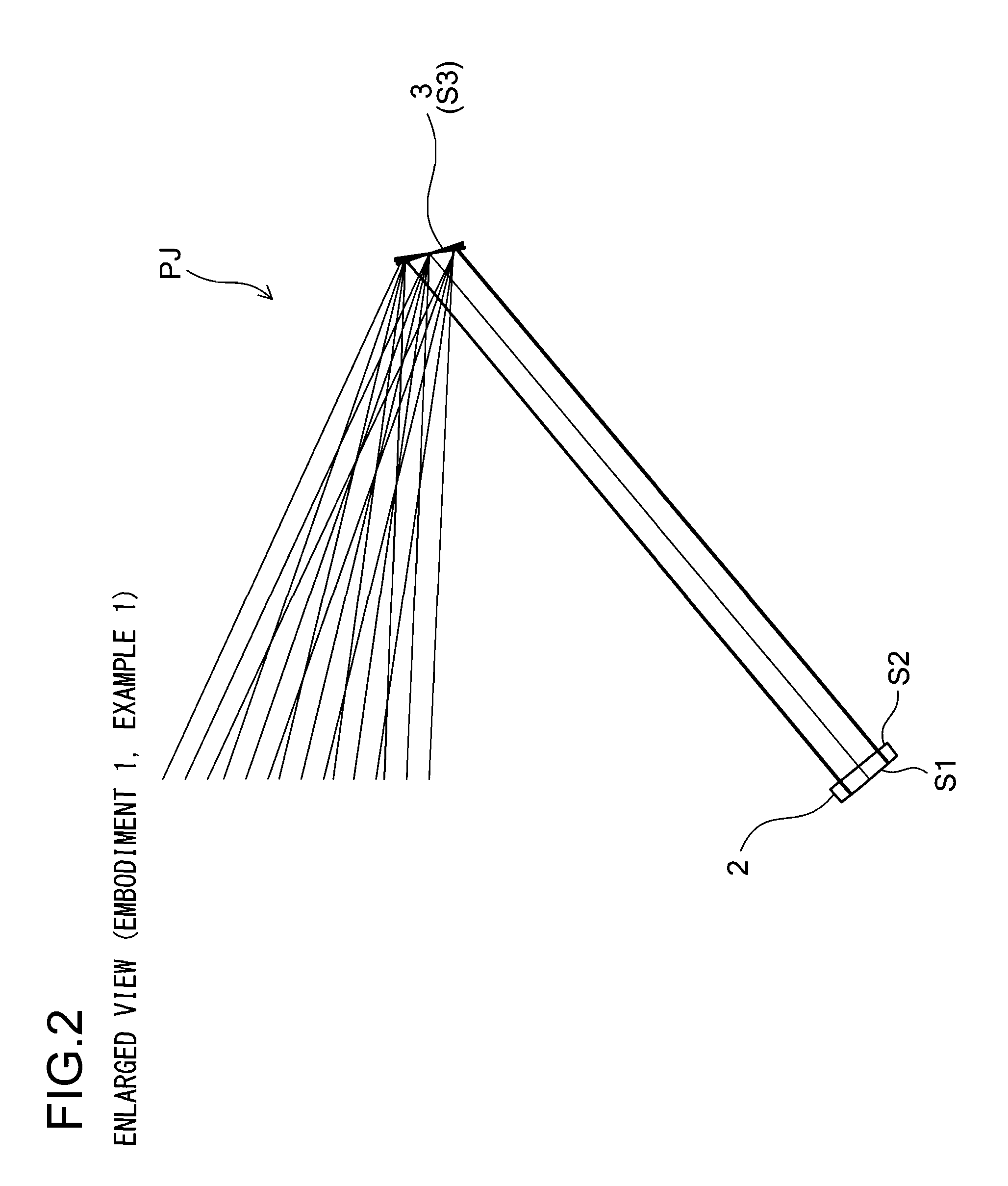
example 1
[0107]
SurfaceNo.SurfacexyzαS1light incidence surface of incidence optical system0000(reference surface)S2light emission surface of incidence optical system000.50S3deflection apparatus (reflection surface (also as an0020−27aperture stop))S4screen surface0208.4115−131.42−40.0381Surface NoRNdνdS1147.88551.516865.26S2∞
example 2
[0108]
SurfaceNo.SurfacexyzαS1light incidence surface of incidence optical system0000(reference surface)S2light emission surface of incidence optical system000.50S3deflection apparatus (reflection surface (also as an0020−15aperture stop))S4screen surface0128.8792−203.225−15.9067Surface NoRNdνdS1148.23631.516865.26S2∞
example 3
[0109]
SurfaceNo.SurfacexyzαS1light incidence surface of incidence optical system0000(reference surface)S2light emission surface of incidence optical system000.50S3deflection apparatus (reflection surface (also as an0020−35aperture stop))S4screen surface0240.5985−67.5707−57.53Surface NoRNdνdS1146.64211.516865.26S2∞
PUM
 Abstract
Description
Claims
Application Information