Optical scanning device and image forming apparatus including the same

a scanning device and image forming technology, applied in the field of optical scanning devices, can solve the problems of reducing the leeway in the design of filters, complicating the manufacturing of filters, and insufficient to improve the light amount distribution, so as to simplify the design and manufacture of optical systems, the effect of simplifying the design and manufacture of ligh

Active Publication Date: 2011-06-09
SHARP KK
View PDF15 Cites 10 Cited by
  • Summary
  • Abstract
  • Description
  • Claims
  • Application Information

AI Technical Summary

Benefits of technology

[0067]With this embodiment, by merely setting the light amounts of two points, correction of the light amount distribution for scanning direction positions on the scanning surface can be easily ach

Problems solved by technology

The following problems exist in conventional optical scanning devices comprising an overfilled optical system.
In this overfilled scanning optical system, since the filter is used exhibiting an optical transmissivity distribution of the opposite shape (curved shape) to the mountain shaped light amount distribution in the scanning direction on the image surface (scanning surface), the filter has to be designed and manufactured to achieve a curved shaped optical transmissivity distribution aligned with slight changes in the light amount distribution, which correspondingly reduces leeway in the filter design and complicates the manufacturing of the filter, and thus there is a problem that the design and manufacture of the optical system is complicated.
Generally, it is common for these filters to involve using a deposition method to form a light-shielding material as a film onto an optically transmissive member such as a glass plate, and in this case it is insufficient to improve the light amount distribution of the mountain shape, and unfortunately time and effort are required to manufacture a filter that exhibits the optical transmissivity distribution of the curved shape.
For example, when forming a film on the optically transmissive member, even though measures are attempted such as depos

Method used


Image

  • Optical scanning device and image forming apparatus including the same
  • Optical scanning device and image forming apparatus including the same
  • Optical scanning device and image forming apparatus including the same

Examples


first embodiment

[0174]Accordingly, in a first embodiment, the light amount of the laser beam L outputted by laser diode 311 is controlled in a following manner.

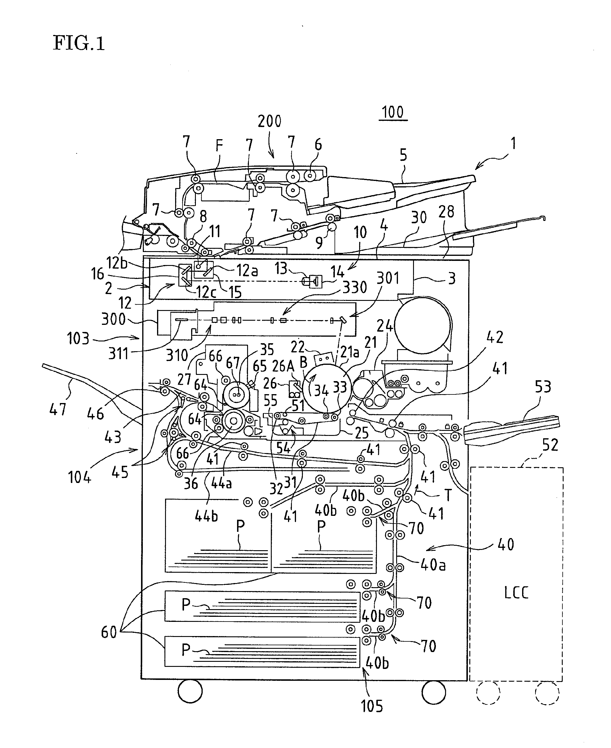
[0175]FIG. 6 is a system block diagram that centrally shows a control portion 50 in the image forming apparatus 100 shown in FIG. 1.

[0176]The control portion 50 is provided with a microcomputer 56 and a storage portion 57, for example. The storage portion 57 includes a ROM (read only memory), a RAM (random access memory), and a nonvolatile memory.

[0177]The ROM stores a control program, which is procedures for processing to be executed by the microcomputer 56. The RAM provides a work area for operations. The nonvolatile memory backs up and holds data required in control, and holds light amount data Q1 and Q2, which are described later.

[0178]It should be noted that the control portion 50 is provided with input circuits including an input buffer and an A / D conversion circuit, which are circuits for inputting input signals from members such as v...

second embodiment

[0214]In a second embodiment, instead of the configuration of the first embodiment in which the slope of the gradient straight line Q is set in advance, a configuration is used in which the slope of the gradient straight line Q can be detected at any time.

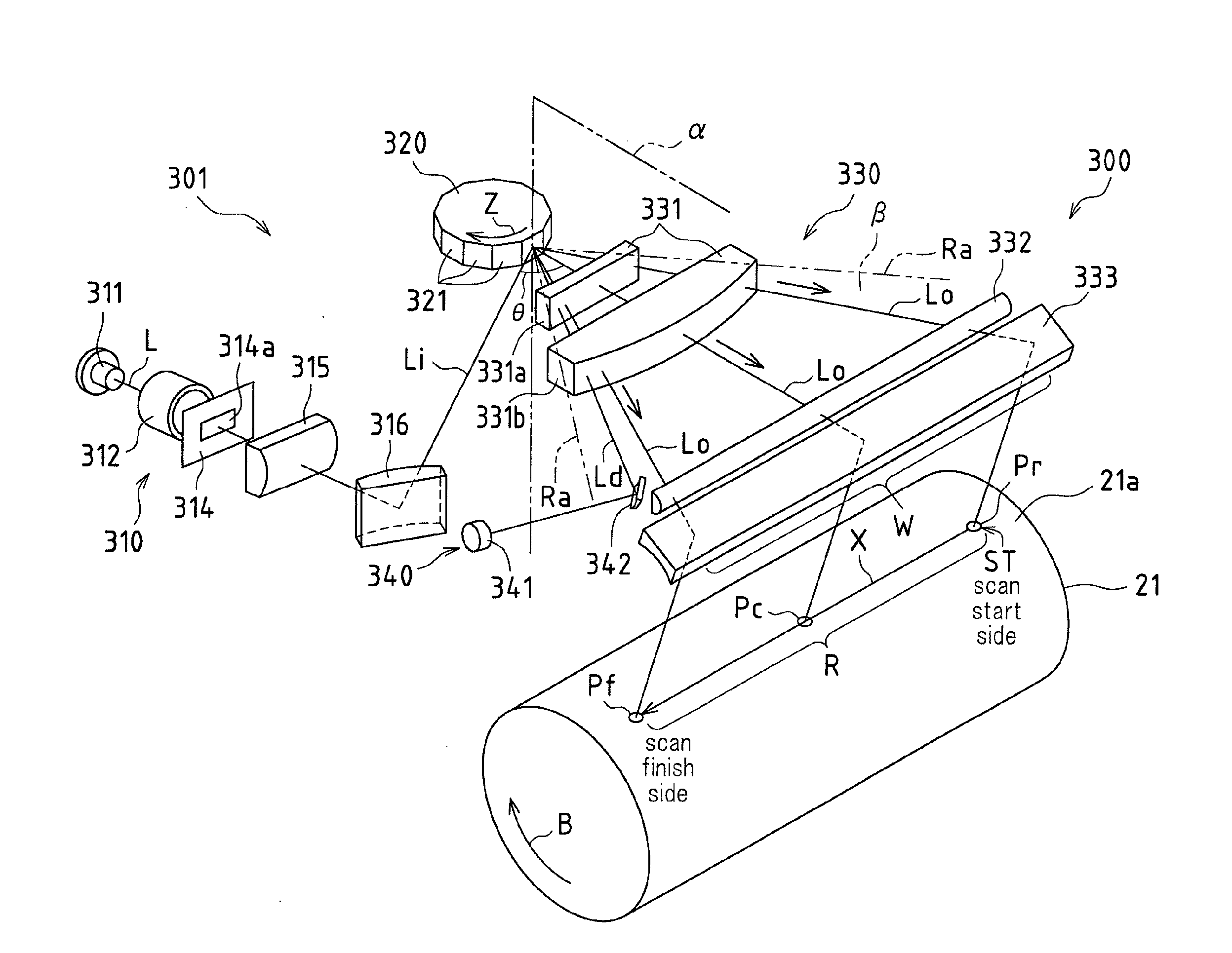
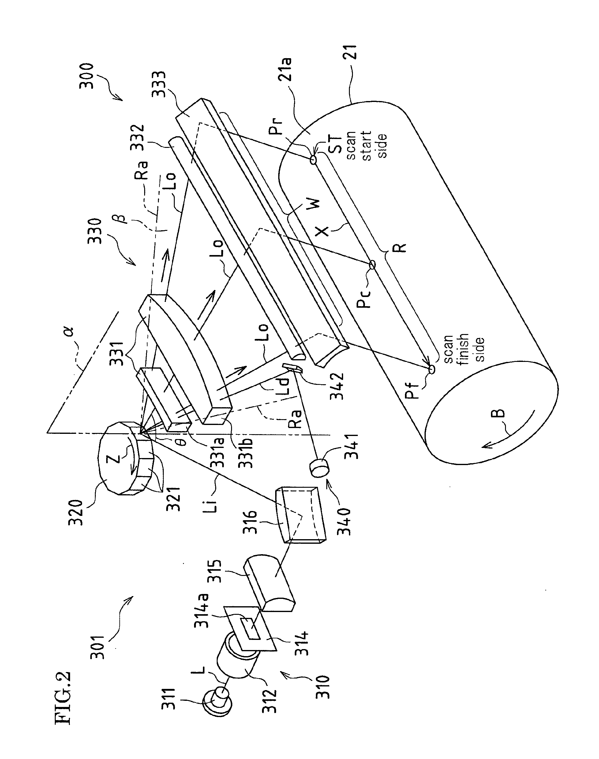
[0215]FIG. 11 is a perspective view schematically showing a configuration of a laser scanning device 300a according to the second embodiment.

[0216]The laser scanning device 300a shown in FIG. 11 is provided with a beam detecting portion 350 in addition to the beam detecting portion 340 in the laser scanning device 300 shown in FIG. 2. That is, the laser scanning device 300a is further provided with a beam detecting portion 350 that detects the outgoing beam Lo at the scan start side of the scanning surface 21a.

[0217]Same reference symbols are assigned to configurations in the laser scanning device 300a shown in FIG. 11 that are the same in the laser scanning device 300 in FIG. 2, and description thereof is omitted.

[0218]In the sec...

third embodiment

[0225]As a different example of correcting the light amount distribution y (see FIG. 5) for the scanning direction X positions on the scanning surface 21a, instead of the configuration in the first embodiment in which the light emission amount of the laser diode 311 is controlled, in a third embodiment, a first light amount correction filter 360 is arranged.

[0226]FIG. 12 is a perspective view schematically showing a configuration of a laser scanning device 300b according to the third embodiment.

[0227]In the laser scanning device 300b shown in FIG. 12, a first light amount correction filter 360 is arranged on an optical path between the rotating multifaceted mirror 320 and the photosensitive drum 21 (here, between the f-theta lens 331 and the second cylindrical lens 332) instead of performing control of the light emission amount of the laser diode 311 in the laser scanning device 300 shown in FIG. 2.

[0228]In the third embodiment, the first light amount correction filter 360 is a comp...


PUM


Abstract

One embodiment of an optical scanning device according to the present invention is directed to an optical scanning device comprising an overfilled optical system in which an incoming beam of a light beam from a light source formed wider than a width in a rotation direction of a reflective surface of a rotating multifaceted mirror is caused to be incident on the reflective surface, and a scanning surface of a scanning object is scanned by an outgoing beam reflected by the reflective surface, wherein the incoming beam is caused to be incident on the reflective surface of the rotating multifaceted mirror in a state having an angle with respect to a virtual vertical surface that is vertical to the scanning surface and vertical to a scanning direction of the outgoing beam, and a light amount distribution for positions on the scanning surface in the scanning direction is corrected based on a slope of a straight line that expresses a ratio of change of light amounts for positions on the scanning surface in the scanning direction when scanning the scanning surface using the outgoing beam.

Description

CROSS-REFERENCE TO RELATED APPLICATIONS[0001]This application claims priority under 35 U.S.C. §119(a) on Patent Application No. 2009-276562 filed in Japan on Dec. 4, 2009, the entire contents of which are herein incorporated by reference.BACKGROUND OF THE INVENTION[0002]The present invention relates to optical scanning devices that can be applied in image forming apparatuses such digital copiers, printers, and fax machines, and to image forming apparatuses.[0003]Conventionally this type of optical scanning device has been installed in image forming apparatuses such as digital copiers, printers, and fax machines, and has been widely used as an optical writing means in these image forming apparatuses.[0004]In these image forming apparatuses provided with optical scanning devices, in a case where image forming is to be performed using an electrophotographic image forming process for example, a surface of an image carrier (a photosensitive body or the like for example) acting as a scann...

Claims


Application Information

Patent Timeline
IPC IPC(8): G02B26/12
CPCG02B26/127G03G15/0409G03G15/326G03G15/0435H04N1/12H04N2201/0082H04N1/1135
Inventor MOTOYAMA, TAKAHARUSHIRAI, NOBUHIRO
Owner SHARP KK
Why Eureka
Try Eureka