Process for fabricating MEMS devices

a technology of mems devices and manufacturing processes, applied in microelectromechanical systems, electrostatic motors, instruments, etc., can solve the problems of increasing the force requirement, causing snap-down, and generating electric force across a relatively large gap

Inactive Publication Date: 2011-06-09
CROSSFIBER +1
View PDF7 Cites 25 Cited by
  • Summary
  • Abstract
  • Description
  • Claims
  • Application Information

AI Technical Summary

Problems solved by technology

One problem with this pad-type actuator, however, is that an electric force is generated across a relatively large gap between the pad and the backside of the mirror.
This large gap effectively decreases the amount of force available to move the mirror, resulting in an increased force requirement, necessitating an increase in system voltage and power to drive the actuator pads.
Moreover, with pad-type actuators snap-down can occur due to electrostatic instability occurring because the force from the pad can increase faster that the restoring force from the spring.
Another problem with the above discussed pad-type actuator is that there is no independent control of movement around the two axes in which the mirrored surface rotates.
This coupled movement severely limits the angle of scan that can be achieved by the mirror.
An additional problem with the coupled movement is that disturbances are harder to correct because damping must occur on both axes.
Damping must be applied to the non-disturbed axis as well, because movement around the axes are not independent of each other.

Method used


Image

  • Process for fabricating MEMS devices
  • Process for fabricating MEMS devices
  • Process for fabricating MEMS devices

Examples


Embodiment Construction

I. Structural Overview

[0019]Although some of the embodiments of the present invention are discussed in terms of optical switching and mirror structures, it is understood and contemplated that the present invention has application in a variety of fields where the use of MEMS technology is desirable. For example, certain embodiments of the present invention may be embodied in electrical devices such as relays and tunable RF filters, in microfluidic devices such as pumps and valves, in actuating and / or scanning devices, or in other devices such as sensors, displays, readers, or equipment such as cameras or medical devices, etc.

[0020]The MEMS comb drive actuator of certain embodiments of the present invention allow a wide range of movement and / or accurate positioning of a structure. This allows the actuator to be used in several different applications where such wide range of movement and / or positioning is needed.

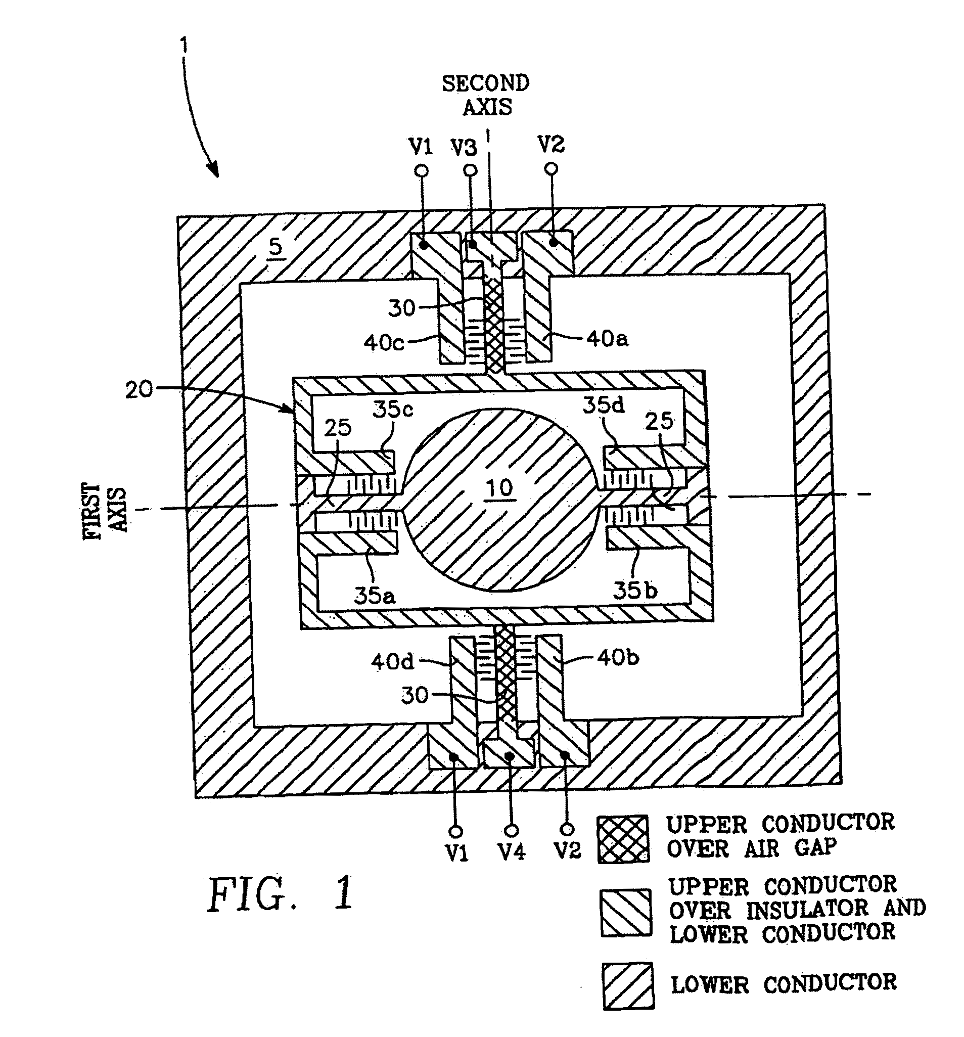
[0021]FIG. 1 is a top view of a simplified example of a MEMS torsional com...


PUM


Abstract

A process for fabricating a MEMS device with movable comb teeth and stationary comb teeth. A single mask is used to define, during a series of processing steps, the location and width of both movable comb teeth and stationary comb teeth so as to assure self alignment of the comb teeth. MEMS devices are fabricated from a single multi-layer semi-conductor structure of semiconductor material and insulator material. In a preferred embodiment the process is employed to provide a MEMS mirror device having a movable structure, a movable frame, a first set of two torsional members, a first set of at least four comb drives, an outer fixed frame structure, a second set of two torsional members, and a second set of at least four comb drives.

Description

CROSS REFERENCE TO RELATED APPLICATIONS[0001]This application is a continuation in part of Ser. No. 10 / 319,403 filed Dec. 1, 2002 which claimed the benefit of Ser. No. 60 / 340,318 filed Dec. 13, 2001, Ser. No. 60 / 340,677 filed Dec. 13, 2001 and was a continuation in part of Ser. No. 10 / 191,041 filed Jul. 2, 2002 and Ser. No. 10 / 190,083 filed Jul. 2, 2002.FIELD OF THE INVENTION[0002]The present invention relates to micro-electro-mechanical systems (MEMS) which are made up of several micro-machined electrical-mechanical structures having sizes typically in the range of millimeters or smaller.BACKGROUND OF THE INVENTION[0003]Microelectromechanical systems (MEMS), which are made up of several micromachined electrical-mechanical structures, have a size typically on a millimeter scale or smaller. These micromachined structures are used to produce MEMS devices that are used in a wide variety of applications including, for example, sensing, electrical and optical switching, and micromachiner...

Claims


Application Information

Patent Timeline
Patent Type & Authority Applications(United States)
IPC IPC(8): H01L21/02
CPCB81B2201/025B81B2201/042B81B2203/0136H02N1/006B81C1/00182G02B26/0841G02B26/101B81B2203/058
Inventor GRITTERS, JOHNKRUGLICK, EZEKIEL JOHN JOSEPHLAST, MATHEW
Owner CROSSFIBER
Why Eureka
Try Eureka