Superimposed Computer Room Building and Process for Cooling this Building

a computer room and superimposed technology, applied in the field of data centres, can solve the problems of large volume, strong air pressure drop considering the recycled air circuit, and inability to provide good control of air temperature at the server level

Inactive Publication Date: 2011-06-16
ENIA ARCHITECTES +1
View PDF38 Cites 69 Cited by
  • Summary
  • Abstract
  • Description
  • Claims
  • Application Information

AI Technical Summary

Benefits of technology

[0054]In a variant of implementing the mid-season operation mode, the air from the exhaust column is completely vented to the outside and all air blown into the supply column is from the outside chilled and / or treated air. In this operation variant, hot air is preferably but not exclusively evacuated through the high exhaust vents to take advantage of natural convection.

Problems solved by technology

Such a conception of the computer room however has the disadvantage of requiring the use of a large volume for a small number of servers and does not provide good control of air temperature at the server level.
However, the Japanese system has the disadvantage of requiring the use of an air conditioning system and a raised floor for each computer room and causing strong air pressure drops considering the recycled air circuit.

Method used


Image

  • Superimposed Computer Room Building and Process for Cooling this Building
  • Superimposed Computer Room Building and Process for Cooling this Building
  • Superimposed Computer Room Building and Process for Cooling this Building

Examples


Embodiment Construction

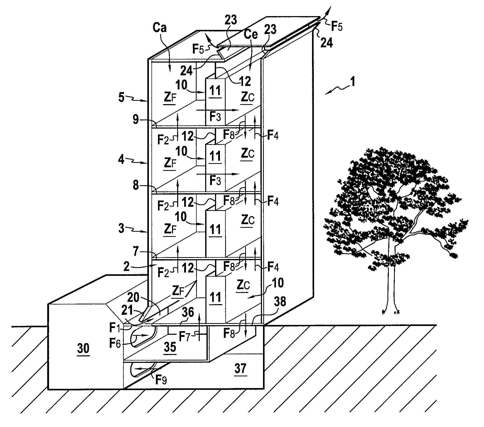
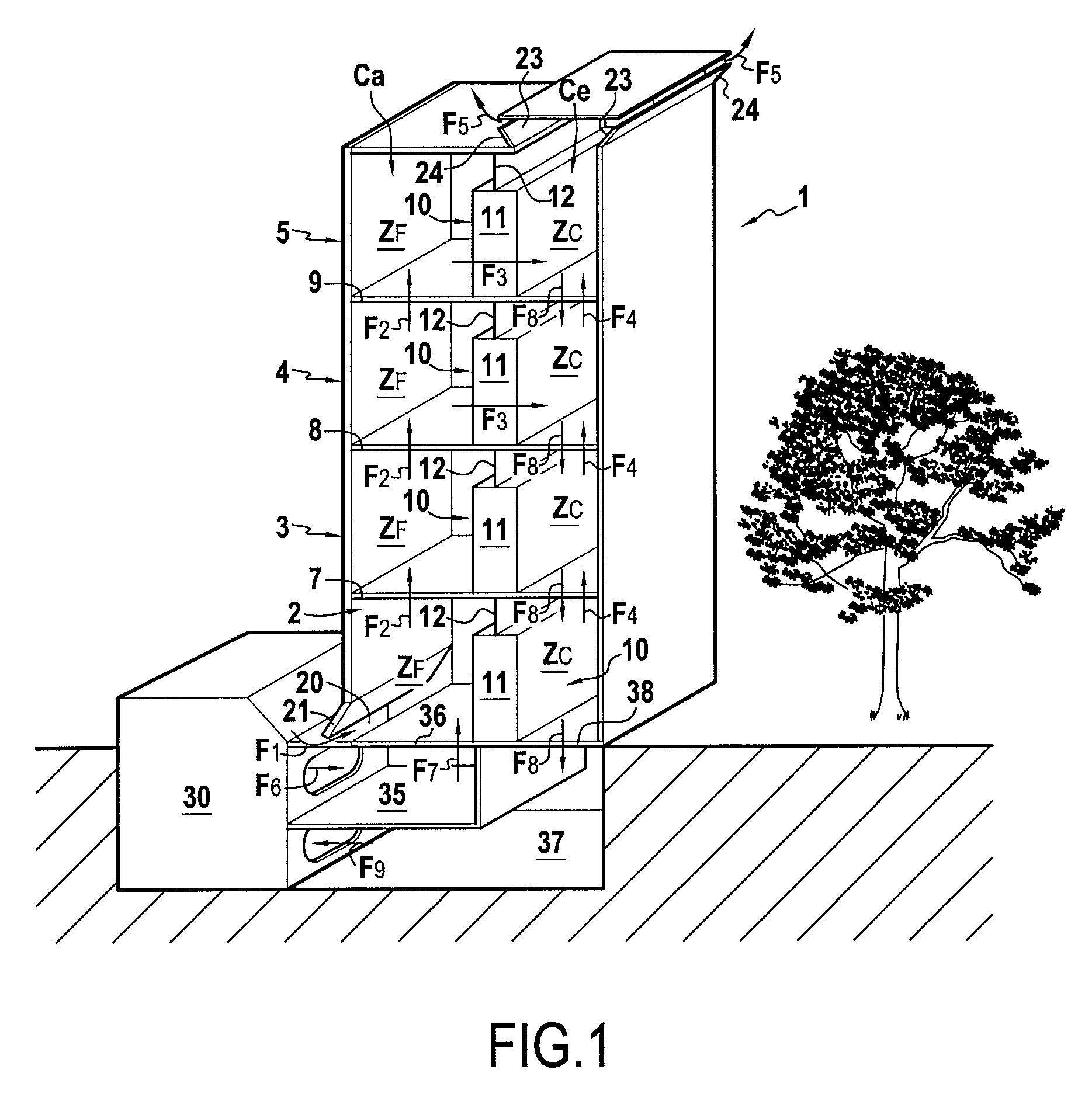
[0064]A building according to the invention, as shown in FIG. 1, 2 and generally designated by reference 1, comprises at least two and, according to the example in FIG. 1, four superimposed computer rooms 2, 3, 4, 5, on the understanding that building 1 could comprise more than four superimposed computer rooms. Each computer room is limited by a peripheral wall 6 which, in the example shown, is common to all computer rooms and forms an outer load-bearing wall of building 1. Thus, in this case, all the computer rooms 2, 3, 4, 5 have the same shape and the same inside surface area. Computer rooms 2, 3, 4 and 5 are also separated from each other by intermediate floors 7, 8, 9.

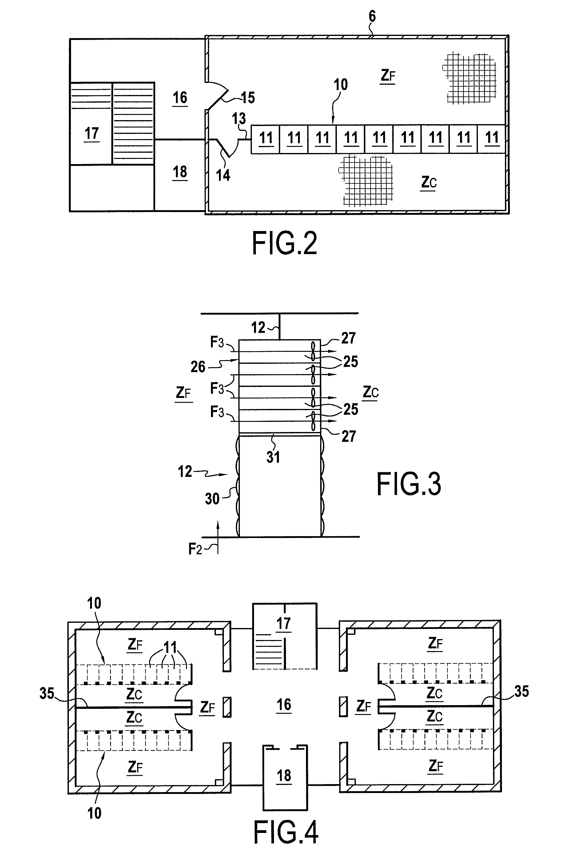
[0065]Each computer room also comprises an inner wall 10 which is partly formed by the juxtaposition of the computer cabinets 11 attached to each other. The inner wall 10 of each computer room is also formed by a top panel 12 which is interposed between the computer cabinets 11 and the ceiling of the corresponding...


PUM


Abstract

Building comprising at least two vertically superimposed computer rooms 2, 3, 4, 5 each limited by a peripheral wall 6 and separated from each other by an intermediate floor 7 and which each contain computer cabinets 11 for computer or electronic equipment 25. The building is characterised in that: each computer room 2, 3, 4, 5 comprises at least one interior wall 10 formed in part or less by the computer cabinets 11 and which separates the interior volume of each computer room into a hot zone Zc and a cold zone Zf, since the air cannot flow between the hot zone Zc and the cold zone Zf without passing through the computer cabinets 11; each intermediate floor 7, 8, 9 is perforated to allow free circulation of air, all cold zones Zf are superimposed and forming a supply column of fresh air Ca and all the hot spots are superimposed forming an exhaust column of hot air Ce; the floors 7, 8, 9, the perimeter walls 6 and interior walls 10 are adapted to prevent a direct flow of air between the supply column Ca and the exhaust column Ce, and the building comprises fresh air means 20, 30 in the supply column Ca and means for evacuating 23, 30 hot air from the exhaust column Ce.

Description

[0001]This application claims priority from French Patent Application No. 09 / 06019 filed Dec. 11, 2009, the disclosure of which is incorporated herein by reference.FIELD OF THE INVENTION[0002]This invention relates to the technical field of data centres, which comprise, on one hand, at least a computer room inside which are arranged servers or other computer or electronic equipment, and means of connection associated communications networks and, on the other hand, means of supplying energy to the servers and means of cooling the computer room. The invention relates more particularly to the field of buildings hosting such data centres.BACKGROUND OF INVENTION[0003]An essential element in the design of these buildings lies in the implementation of systems for cooling servers insofar as hardware manufacturers require relatively low temperature ranges for rooms housing the servers, to maintain the contractual warranty for the equipment. In addition, air conditioning systems for computer ...

Claims


Application Information

Patent Timeline
Patent Type & Authority Applications(United States)
IPC IPC(8): E04F17/04G05D23/13E04B1/00
CPCE04H1/06H05K7/20745E04H2005/005E04H5/02
Inventor CHAZELLE, MATHIEUPALLUBICKI, SIMONPIECHACZYK, BRICEPOMMIER, LAURENTCAZERES, BERNARDAUBE, NICOLAS
Owner ENIA ARCHITECTES
Why Eureka
Try Eureka