Aircraft Engine Fuel Supply

Active Publication Date: 2011-06-16
SN DETUDE & DE CONSTR DE MOTEURS DAVIATION S N E C M A
View PDF19 Cites 22 Cited by
  • Summary
  • Abstract
  • Description
  • Claims
  • Application Information

AI Technical Summary

Benefits of technology

An object of the invention is to provide a supply device for supplying fuel to an aircraft engine, which device

Problems solved by technology

Furthermore, in the event of the vane pump breaking down, fuel is no longer metered.
The mechanic

Method used


Image

  • Aircraft Engine Fuel Supply
  • Aircraft Engine Fuel Supply
  • Aircraft Engine Fuel Supply

Examples


Embodiment Construction

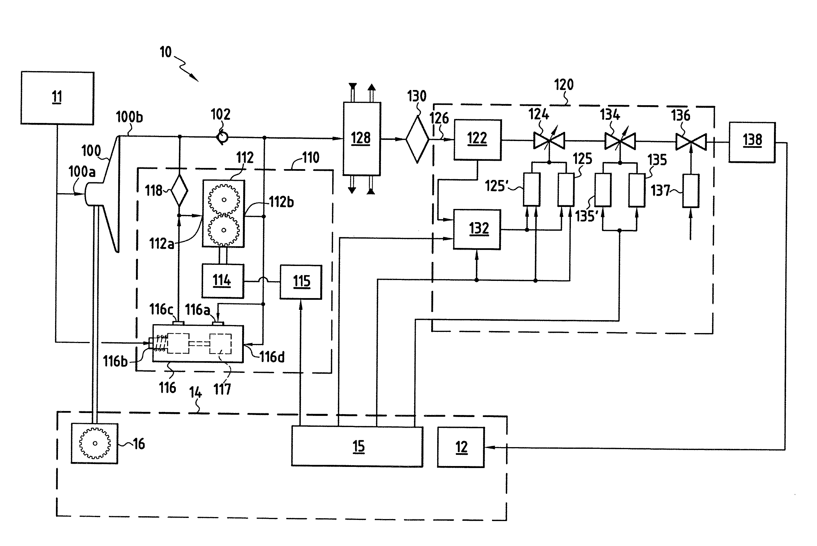
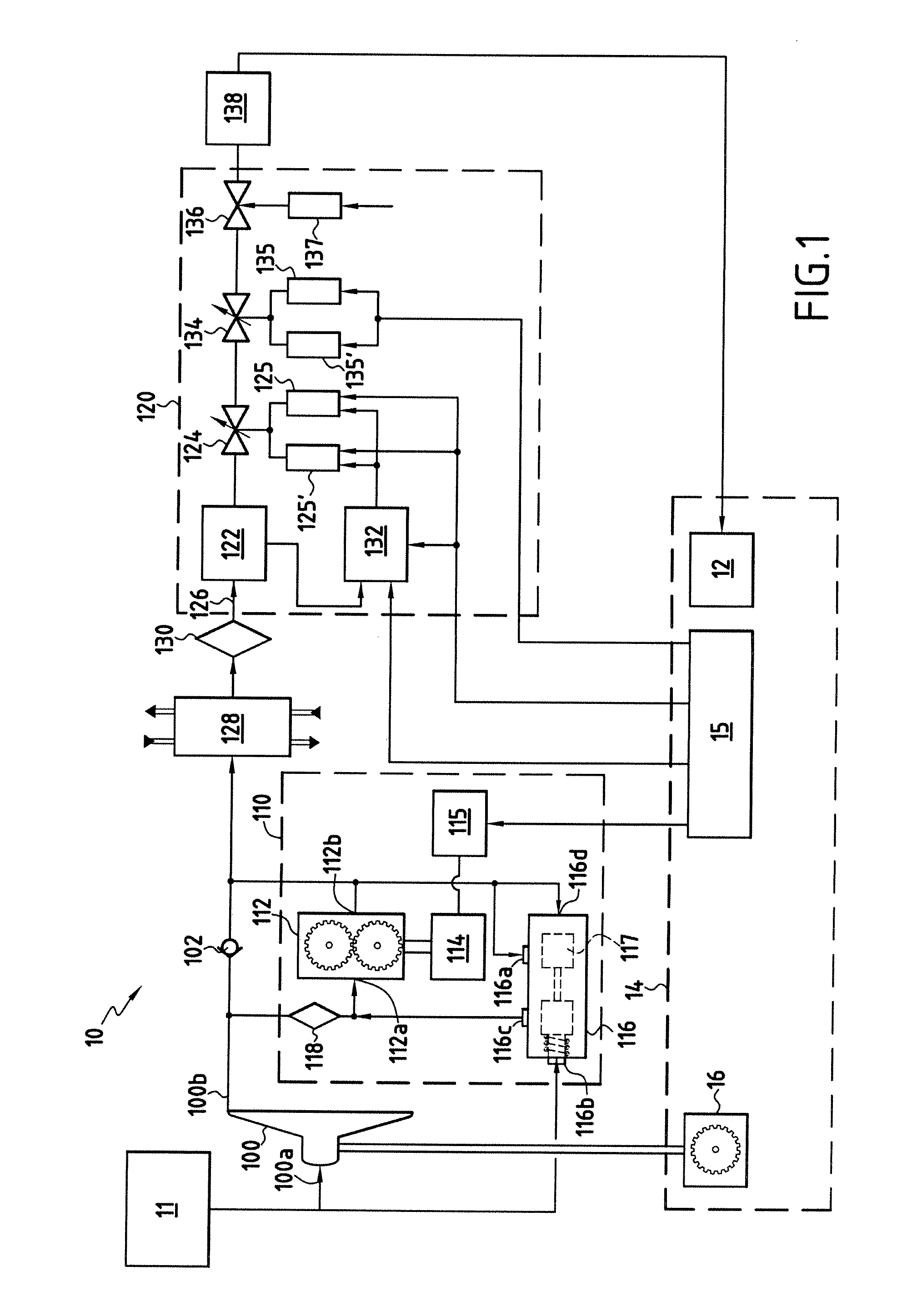
The fuel supply circuit 10 of FIG. 1 receives fuel from an airplane fuel circuit 11 and delivers a flow of fuel to a system 12 for injecting fuel into a combustion chamber of a gas turbine of an engine 14 fitted to the airplane, it being understood that the supply device described may be used for aircraft engines other than gas turbine airplane engines, e.g. helicopter engines.

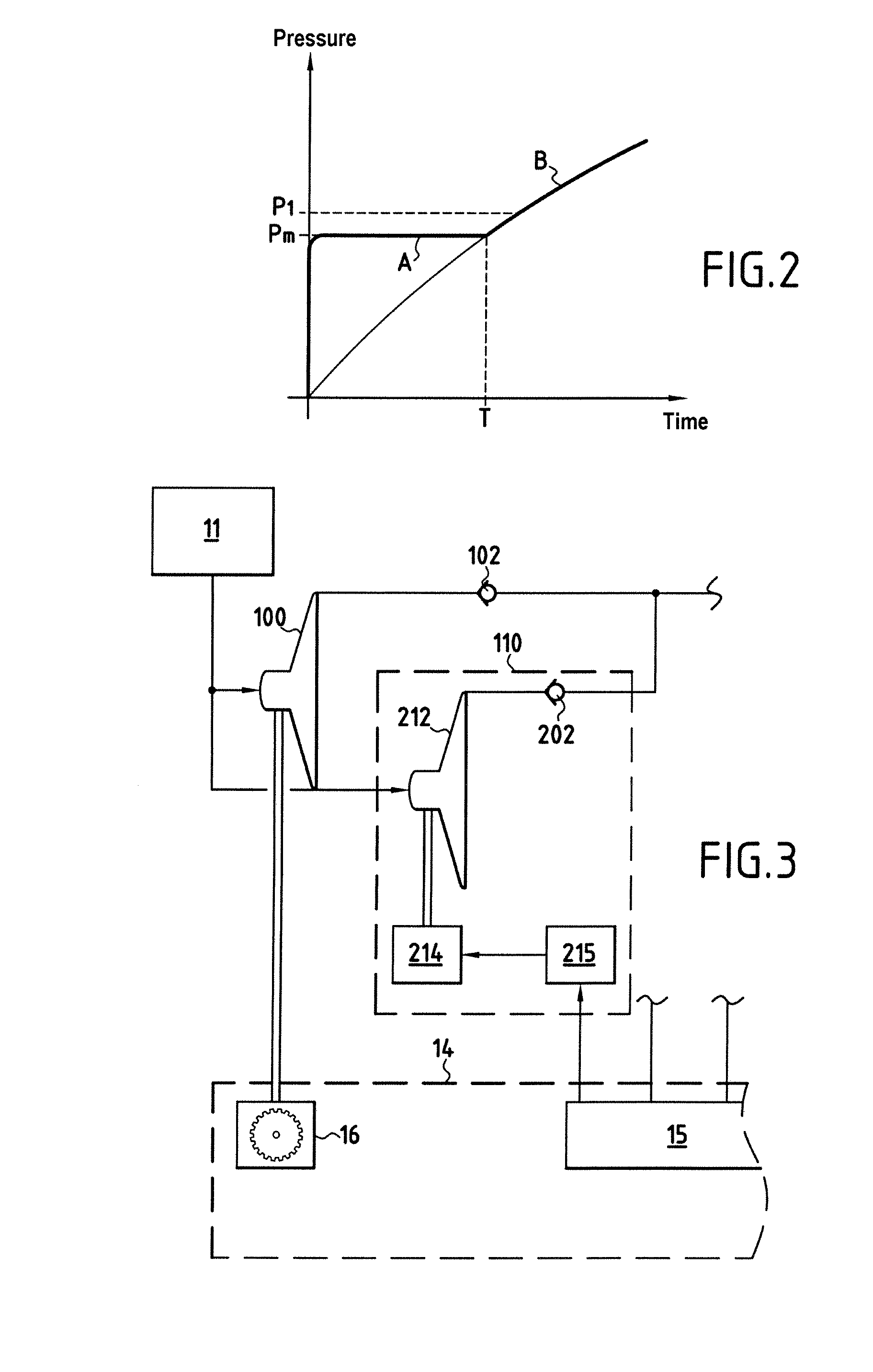
The circuit 10 comprises a centrifugal pump 100 constituting the main pump of the circuit. The pump 100 has an inlet 100a connected to the fuel circuit 11, and a high pressure outlet 100b delivering fuel at a pressure that is a function of the speed of rotation of the pump. The pump is driven by a mechanical connection with the accessory drive module 16 of the engine 14 and which is coupled to the turbine thereof.

An assistance pump unit 110 comprises a positive-displacement pump 112 having an inlet 112a connected to the outlet of the centrifugal pump 100, an electric motor 114 for driving the pump 112 under th...


PUM


Abstract

A centrifugal pump driven by mechanical coupling with an engine has a low pressure inlet receiving fuel from a fuel circuit of an aircraft, a high pressure outlet connected to a regulator circuit for regulating the flow rate of fuel supplied to the engine, and an assistance pump unit that is electrically controlled, having an inlet connected to the aircraft fuel circuit and an outlet connected to the flow rate regulator circuit so as to deliver, via its outlet, fuel that is at a predetermined minimum pressure, the pressure of the fuel supplied to the regulator circuit being the higher of the pressures delivered by the centrifugal pump and the assistance pump unit.

Description

The invention relates to a device for supplying fuel to an aircraft engine, and particularly but not exclusively to a gas turbine airplane engine.It is common practice for such a supply device to include a positive-displacement gear pump driven by the engine via an accessory gear box coupled to a shaft of the engine. The positive-displacement pump receives fuel coming from the fuel circuit of the airplane via a booster pump. An electro-hydraulic metering valve is mounted in a supply pipe connecting the outlet from the positive-displacement pump to a combustion chamber of the engine. A fuel return circuit with a controlled variable-restriction bypass valve is connected between the outlet and the inlet of the positive-displacement pump. The bypass valve is hydraulically controlled to maintain the head loss through the metering valve at a value that is constant or almost constant, thus enabling fuel to be delivered at the desired rate corresponding to the position of the metering valve...

Claims


Application Information

Patent Timeline
IPC IPC(8): F02M59/36F02M37/04F02M37/00
CPCF02C7/22F02C7/236F02C9/28F05D2270/094F05D2270/62F05D2270/304F05D2270/021F05D2260/85
Inventor BROCARD, JEAN-MARIEDELDALLE, REGISGALOZIO, PHILIPPEMARTINI, MICHELVARIZAT, ALAIN
Owner SN DETUDE & DE CONSTR DE MOTEURS DAVIATION S N E C M A
Why Eureka
Try Eureka