Pulse width modulated battery charging

a battery charging and pulse width technology, applied in battery overcharge protection, safety/protection circuits, transportation and packaging, etc., can solve the problems of battery overheating and becoming damaged, cost and space of pre-charge transistors, resistors and other necessary components to control the pre-charge transistors,

Inactive Publication Date: 2011-06-16
TEXAS INSTR INC
View PDF7 Cites 20 Cited by
  • Summary
  • Abstract
  • Description
  • Claims
  • Application Information

AI Technical Summary

Problems solved by technology

Otherwise, if a relatively high charge current is applied to a fully discharged Li-Ion battery, the battery may overheat and become damaged and / or can damage other nearby components.
The disadvantages of these techniques include the cost and space of the pre-charge transistor, the resistor and other necessary components to control the pre-charge transistor.
The disadvantage of this example is that if the voltage of the battery 102 is too low, e.g. almost zero, then it is very likely that the VCC will be pulled down below the minimum operating voltage of the battery management system chip 108, so the status of the battery 102 cannot be updated and battery-protection functions are not operational.
Each time the V_packp overshoots V_fc, however, the battery charging procedure inappropriately enters the fast-charging mode, so the charge current rises to the fast-charge level (I_fc), only to drop back to the pre-charge level (I_pc) when the V_packp drops back below V_fc.
The repeated application of the fast-charge current can cause the severe over-heating problems for the battery 102.
Many commercially available chargers, though, do not have this capability, but will stay in the fast-charge mode once entering it, even if the V_packp drops back below the V_fc, thereby rendering the pre-charge mode completely ineffective.
As design constraints push V_fc ever closer to V_min, however, the cost of manufacturing components that have an appropriate response time or delay period increases.
Additionally, the power consumption of these components also continues to rise leading to a more expensive, less efficient battery charging system.

Method used


Image

  • Pulse width modulated battery charging
  • Pulse width modulated battery charging
  • Pulse width modulated battery charging

Examples


Embodiment Construction

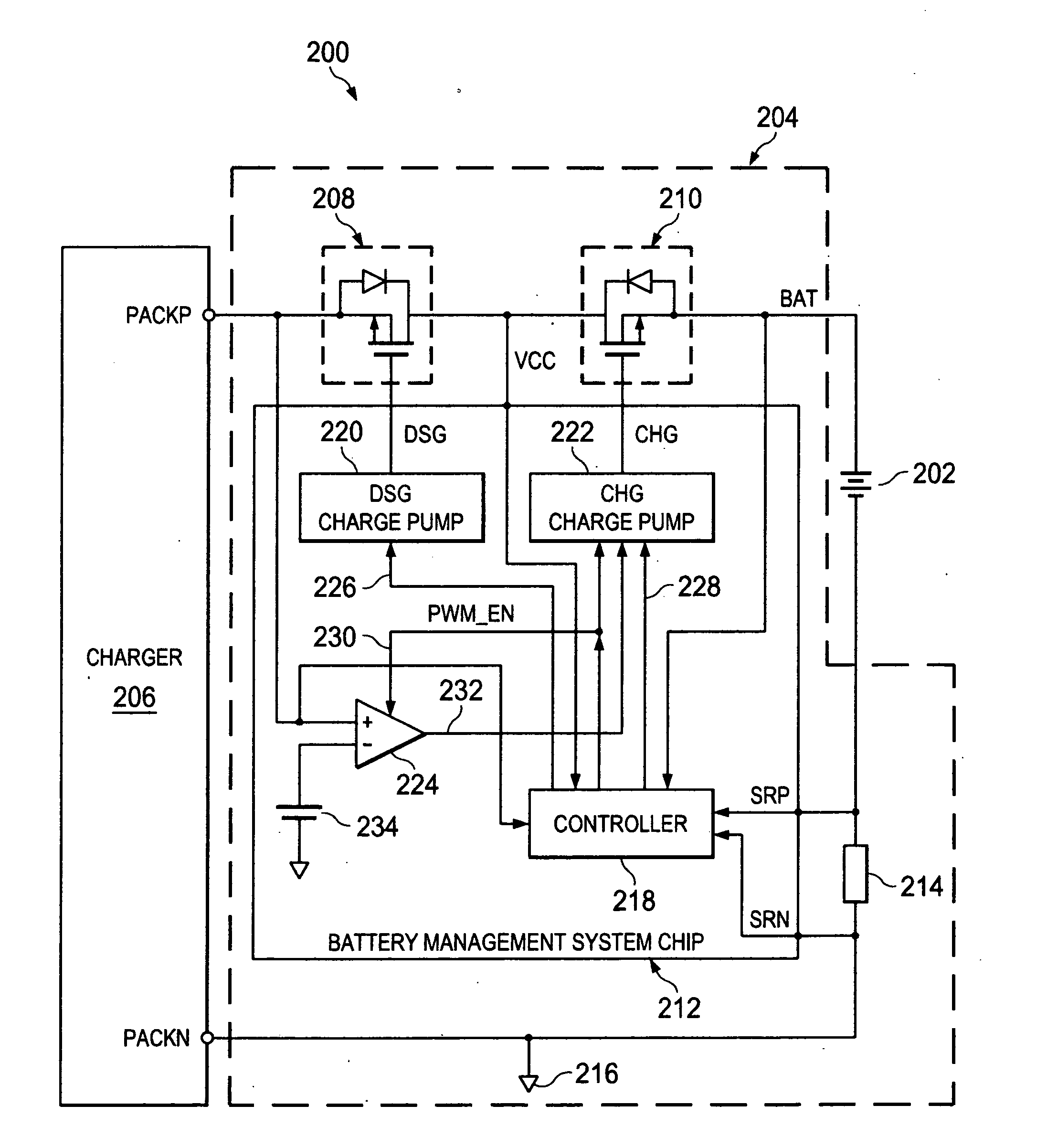
[0022]An example electronic device 200 (e.g. cell phone, PDA, MP3 player, notebook computer, etc.) that operates with a rechargeable battery 202 (such as a Li-Ion battery) under control of a battery management system 204 (incorporating an embodiment of the present invention) between a charger 206 and the battery 202 is shown in a simplified schematic diagram in FIG. 3. The battery management system 204 generally includes a discharge FET 208, a charge FET 210, a battery management system chip 212 and a sense resistor 214. The voltage (at PACKP) from the charger 206 is applied to the battery 202 (at BAT) through the discharge FET 208 and the charge FET 210 under control of the battery management system chip 212. Unlike in the prior art described above, however, the charge FET 210 is controlled by the battery management system chip 212 to turn on and off relatively slowly during the pre-charging mode. Thus, the electrical connection between the voltage (at PACKP) from the charger 206 a...


PUM


Abstract

A battery management system for charging a battery by a charger includes a transistor and either a charge pump or a push-pull output driver. The transistor increases and decreases an electrical connection between the battery and a voltage from the charger and transmits a charge current from the charger to the battery by turning on and off in response to a pulse width modulated drive signal generated by the charge pump or the push-pull output driver. The charge pump or the push-pull output driver increases the drive signal when the voltage from the charger is above a pre-charge threshold voltage and decreases the drive signal when the voltage from the charger is below the pre-charge threshold voltage.

Description

BACKGROUND OF THE INVENTION[0001]Some electronic devices 100 that operate with a rechargeable battery 102 have a battery management system 104 between a charger 106 and the battery 102 for controlling the charging, and sometimes the discharging, of the battery 102, as shown in a simplified prior art schematic diagram in FIG. 1. The battery management system 104 usually includes a battery management system chip 108, with various internal integrated circuit components, along with a discharge FET 110, a charge FET 112 and a sense resistor 114 external to the battery management system chip 108.[0002]The control enabled by the battery management system 104 can be essential for batteries that can overheat or become damaged due to improper charging techniques. For example, when a Li-Ion (Lithium-Ion) battery is fully, or almost fully, discharged, the charge current applied to it during recharging must be considerably smaller than the charge current that can be applied when the battery stil...

Claims


Application Information

Patent Timeline
Patent Type & Authority Applications(United States)
IPC IPC(8): H02J7/00
CPCH02J7/0029H02J2007/004H02J2007/0037H02J7/041H02J7/00302H02J7/00306H02J7/0071H02J7/04
Inventor ZHANG, WEIBIAOHAMLETT, MARK A.COOPER, J. RANDALL
Owner TEXAS INSTR INC
Why Eureka
Try Eureka