Storage rack for fresh or spent nuclear fuel assemblies

a technology for storage racks and nuclear fuel, which is applied in the direction of nuclear elements, nuclear engineering problems, greenhouse gas reduction, etc., can solve the problems of significant risk of rifling damage of neutron-absorbing plates, additional manufacturing and checking operations, and relatively simple sleeves design. , to prevent any risk of criticality, good centering of sleeves

Active Publication Date: 2011-06-16
TN INT (FR)
View PDF14 Cites 15 Cited by
  • Summary
  • Abstract
  • Description
  • Claims
  • Application Information

AI Technical Summary

Benefits of technology

[0009]The invention therefore aims to at least partially resolve the aforementioned drawbacks, relative to the embodiments of the prior art. More specifically, the invention aims to provide a storage rack for nuclear fuel assemblies simultaneously offering high mechanical strength, a small overall mass, as well as a design ensuring easy production and assembly.

Problems solved by technology

In document FR 2 759 484, the design of the sleeves is relatively simple, but can be problematic, given that the fuel assembly is in direct contact with the plates made from a neutron absorbing material.
This situation results in a significant risk of rifling damage of the neutron-absorbing plates during operations for loading and unloading assemblies in the cavity.
In relation to plates with straight edges, these serrations require additional manufacturing and checking operations that do not make it possible to fully meet economic criteria.
Nevertheless, the concept presented in that document has the drawback of using a neutron-absorbing material requiring its confinement between sheets, substantially complicating the production of the sleeves.
The thickness of the walls forming the tubes must then be at least equal to that of the neutron-absorbing plates, which does not make it possible to optimize their thickness and therefore to comply with mass criteria.
Furthermore, the tubes are made using costly machining operations so as to be able to receive the neutron-absorbing plates in the openwork portions.
Lastly, the neutron-absorbing plates undergo discontinuities over a length at least equal to several times their thickness at elements keeping the profiles of the tube in position, which is detrimental to the performance of the sleeves from a criticality perspective by facilitating the neutron interaction between adjacent fuel assemblies.

Method used


Image

  • Storage rack for fresh or spent nuclear fuel assemblies
  • Storage rack for fresh or spent nuclear fuel assemblies
  • Storage rack for fresh or spent nuclear fuel assemblies

Examples


Embodiment Construction

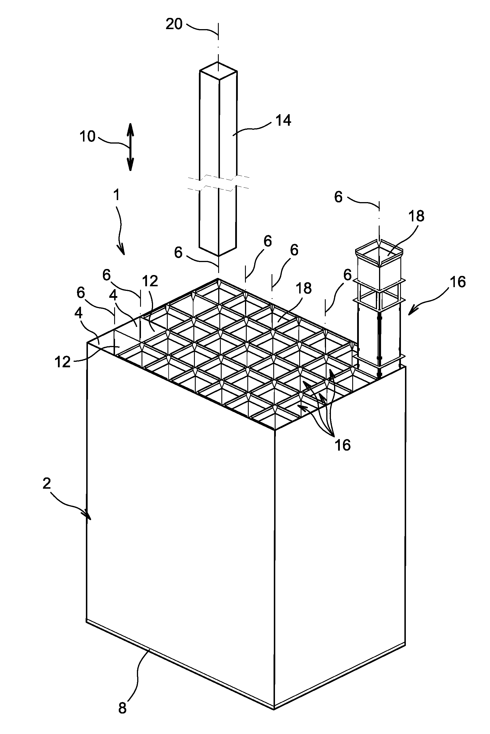
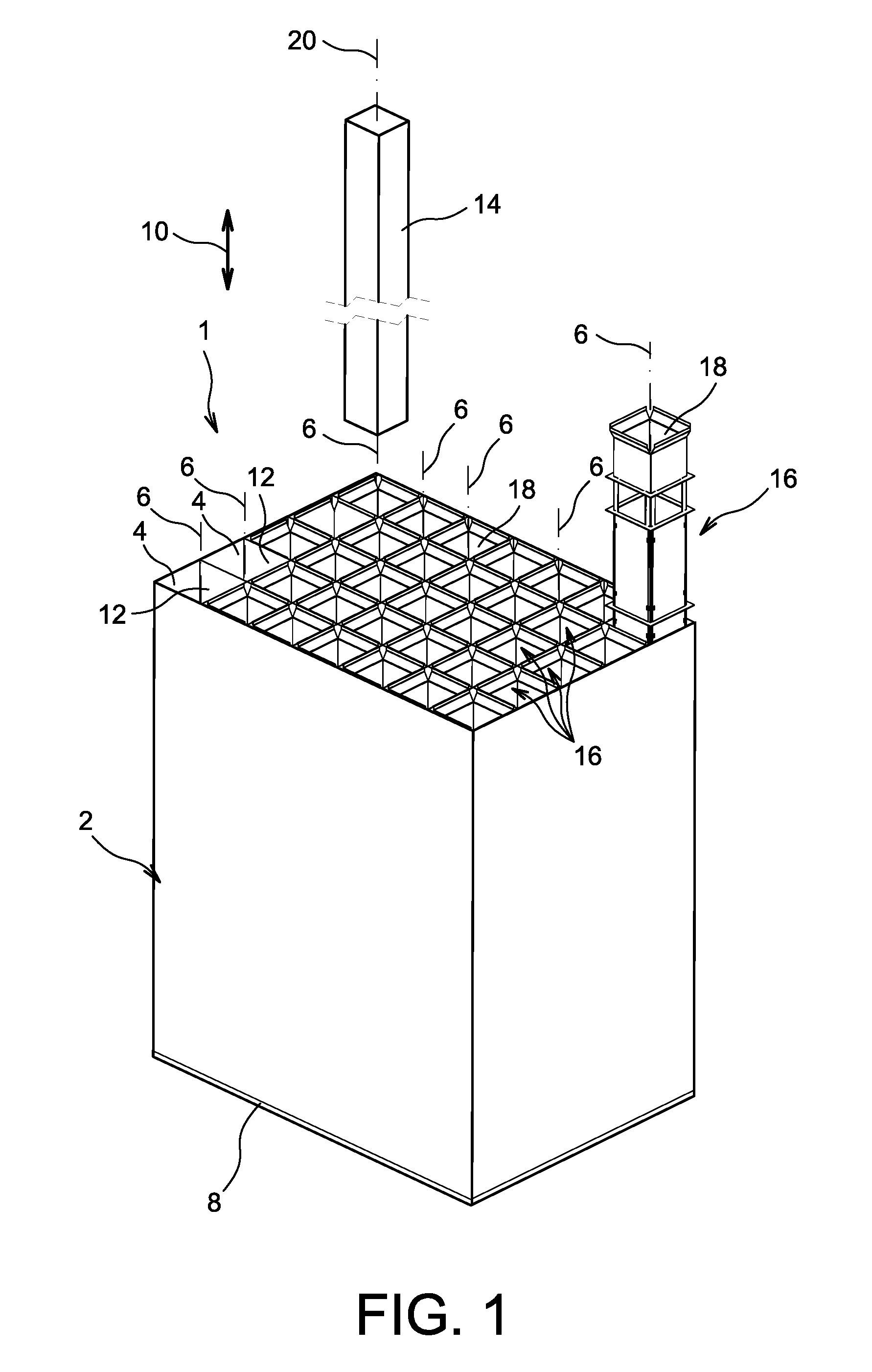
[0040]First in reference to FIG. 1, a storage rack 1 for fresh nuclear fuel assemblies or nuclear fuel assemblies previously spent in a nuclear reactor is shown, the rack being intended to be submerged in a pool.

[0041]This figure shows that the rack 1 first has a rigid structure or “skeleton”2, defining a plurality of cavities or “cells”4 parallel to each other, and axes 6 oriented vertically when the rack 1 is submerged in the pool, with the bottom 8 of the structure 2 resting on the bottom of the pool. In this position shown in the figure, the axes 6, parallel to the longitudinal direction 10 of the rack, are therefore arranged vertically.

[0042]The cells 4, usually provided in large number, such as several dozen, can be obtained in any way known by those skilled in the art, such as that aiming to provide main sheets parallel to each other, separated by crosspiece sheets arranged orthogonally relative thereto. This leads to substantially cylindrical cells 4, each delimited by a sid...


PUM


Abstract

A storage rack for nuclear fuel assemblies, comprising a rigid structure defining a plurality of adjacent cells, and comprising in each cell a sleeve defining a cavity intended to receive a nuclear fuel assembly, the sleeve having, in cross-sectional orthogonal to the longitudinal direction, a generally polygonal shape whereof the sides are produced using plates made from a neutron-absorbing material. According to the invention, the sleeve also includes: profiles each forming a corner piece, arranged on at least several angles of said generally polygonal cross-section, these profiles serving as a mounting bracket for the plates made of a neutron-absorbing material; and a means for maintaining the profiles therebetween.

Description

TECHNICAL FIELD[0001]The present invention generally concerns the field of storage racks for fresh nuclear fuel assemblies or nuclear fuel assemblies previously spent in a nuclear reactor.[0002]The invention is applicable to the storage of all types of nuclear fuel assemblies, in particular those intended for pressurized water reactors (PWR).BACKGROUND OF THE INVENTION[0003]When nuclear fuel assemblies must be stored, they are generally placed in storage racks, submerged in pools. These racks usually have a rigid structure or “skeleton” defining a plurality of cavities or “cells,” parallel to each other and oriented vertically when the rack is submerged in the pool. At least some of these cells receive a sleeve defining a cavity for receiving a nuclear fuel assembly. In order to reduce the distances between each cell as much as possible and thereby increase the storage capacity of the rack, while ensuring the sub-criticality of the latter part when it is loaded with nuclear fuel ass...

Claims


Application Information

Patent Timeline
Patent Type & Authority Applications(United States)
IPC IPC(8): G21C19/07
CPCG21C19/07G21C19/40G21Y2004/30G21Y2002/303G21Y2002/50G21Y2002/207Y02E30/30
Inventor FOUSSARD, GUILLAUMEANDRE, REGIS
Owner TN INT (FR)
Why Eureka
Try Eureka