Modified ply drops for composite laminate materials

a technology of composite laminate materials and droplets, which is applied in the direction of engine components, machines/engines, domestic applications, etc., can solve the problems of voids or low strength within the laminate, affecting the structural integrity of the laminate, and reducing the strength of the lamina

Inactive Publication Date: 2011-06-16
GENERAL ELECTRIC CO
View PDF5 Cites 33 Cited by
  • Summary
  • Abstract
  • Description
  • Claims
  • Application Information

AI Technical Summary

Problems solved by technology

However, depending on the desired configuration of the component being manufactured, it is often necessary to taper the thickness of the laminate.
However, while such a straight edge provides for efficient thickness tapering of a laminate 10, this geometry also has detrimental impact on the structural integrity of the laminate 10.
This may be particularly true when the gap 22 (FIG. 1) created at the ply drop 12 is inadequately filled with matrix material during subsequent processing of the laminate 10, which results in a void or area of low strength within the laminate.
As such, the conventional straight edged ply drop 12 results in a substantial reduction in the strength of the laminate 10 at the ply drop 12, which can eventually lead to failure of the laminate 10 through delamination and / or cracking of the matrix material 18.

Method used


Image

  • Modified ply drops for composite laminate materials
  • Modified ply drops for composite laminate materials
  • Modified ply drops for composite laminate materials

Examples


Embodiment Construction

[0026]Reference now will be made in detail to embodiments of the invention, one or more examples of which are illustrated in the drawings. Each example is provided by way of explanation of the invention, not limitation of the invention. In fact, it will be apparent to those skilled in the art that various modifications and variations can be made in the present invention without departing from the scope or spirit of the invention. For instance, features illustrated or described as part of one embodiment can be used with another embodiment to yield a still further embodiment. Thus, it is intended that the present invention covers such modifications and variations as come within the scope of the appended claims and their equivalents.

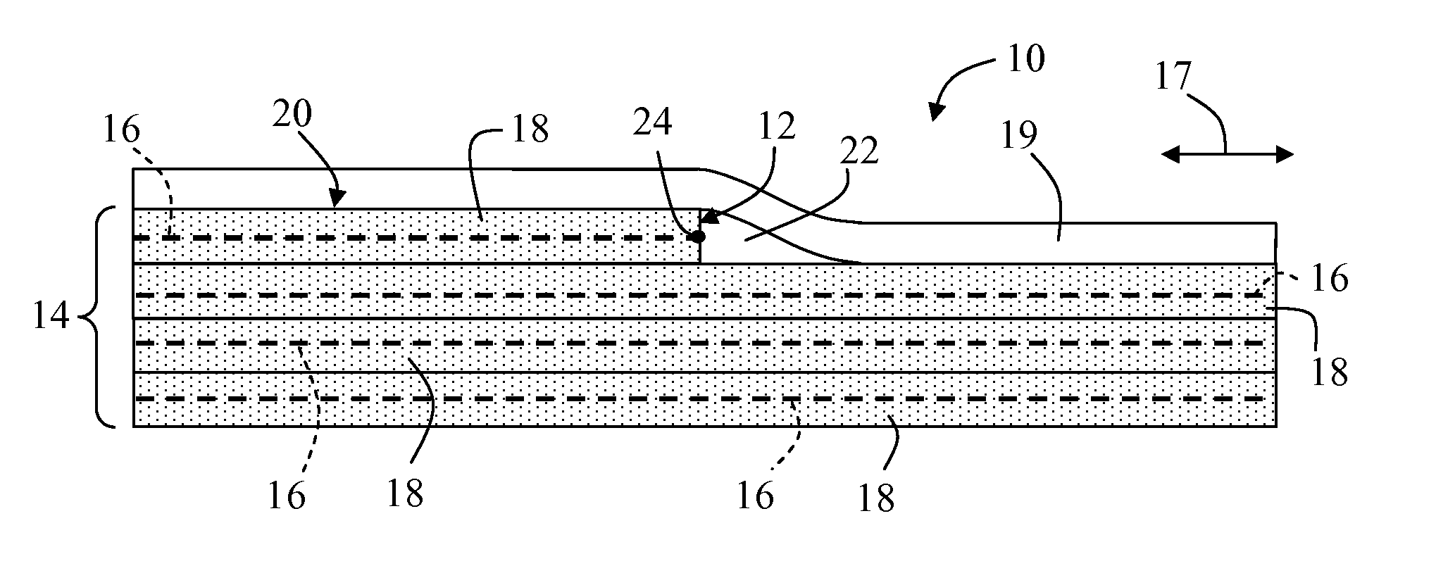
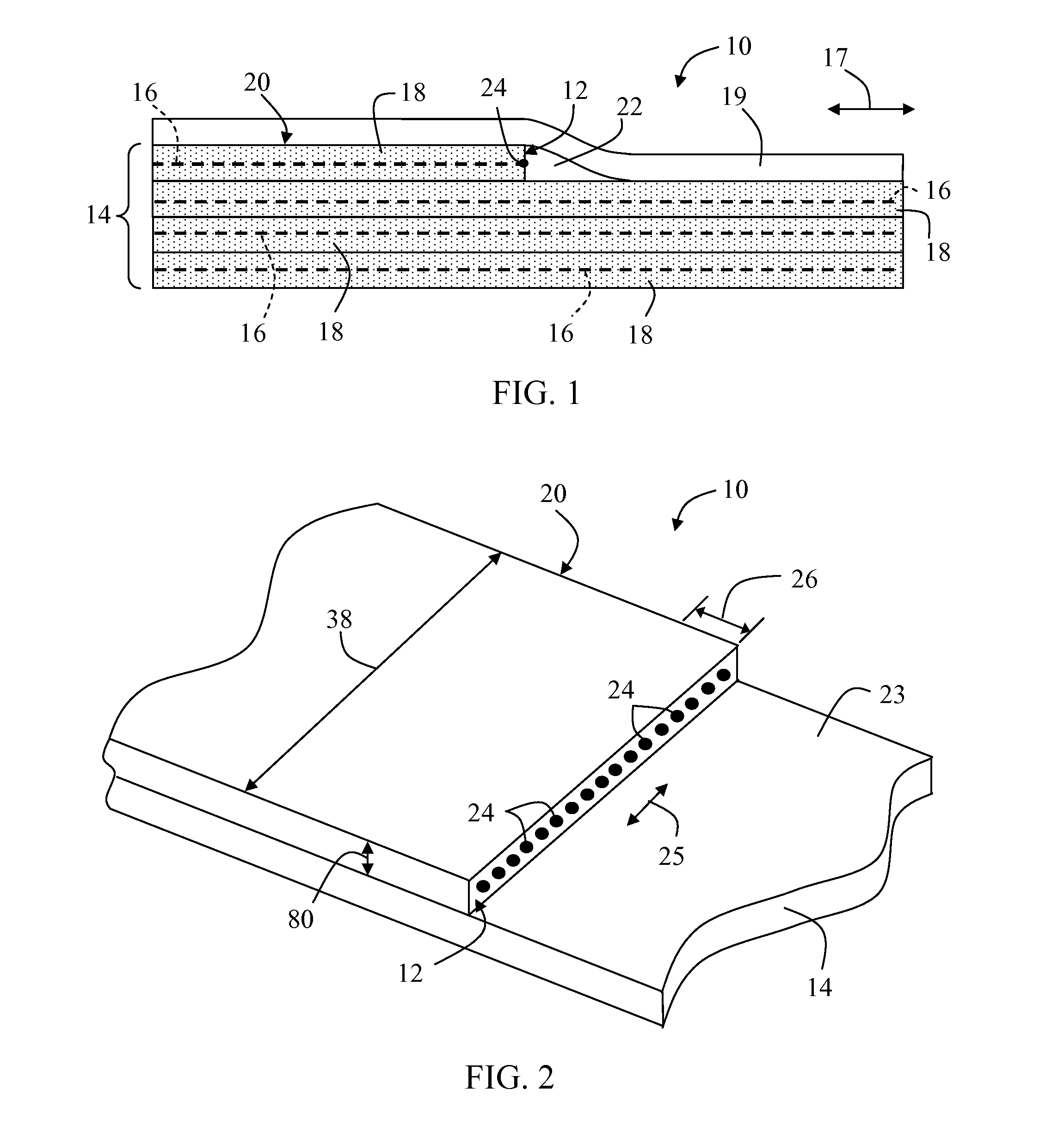
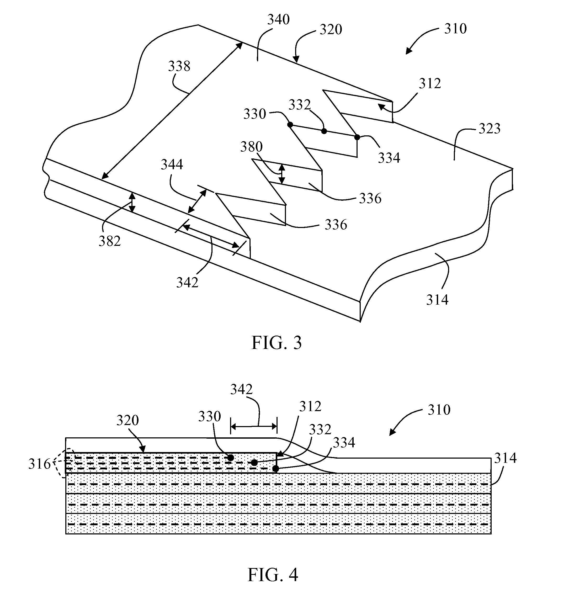
[0027]The present subject matter is generally directed to composite laminate materials (“laminates”) including modified ply drops configured to reduce stress concentrations within the laminate. For example, it is believed that, by spreading out the terminat...


PUM

PropertyMeasurementUnit
depthaaaaaaaaaa
taper angleaaaaaaaaaa
stress concentrationaaaaaaaaaa

Abstract

A composite laminate material is disclosed. The composite laminate material includes a plurality of adjacently disposed plies. At least one of the plies is configured as a terminated ply. Additionally, a ply drop is defined by the terminated ply, wherein the ply drop is modified to reduce stress concentrations within the composite laminate material.

Description

FIELD OF THE INVENTION[0001]The present subject matter relates generally to composite laminate materials and, more particularly, to modified ply drops for reducing stress concentrations within composite laminate materials.BACKGROUND OF THE INVENTION[0002]Composite laminate materials (“laminates”) generally consist of a plurality of layers or plies of composite material assembled together to provide the laminate with improved engineering properties. Each ply typically includes a reinforcement material surrounded by and supported within a matrix material. With regard to fiber-reinforced laminates, reinforcement materials generally include high-strength fibers, such as glass or carbon fibers, with suitable matrix materials including various polymer or resin materials, such as such epoxy, polyester or vinyl ester resins. Typically, known reinforcement materials are designed to have both high static and fatigue strengths and, thus, can provide superior stiffness and strength to component...

Claims


Application Information

Patent Timeline
Patent Type & Authority Applications(United States)
IPC IPC(8): B32B3/26
CPCB29C70/30B29L2031/082B32B3/02B32B5/26B32B2603/00B32B3/04B32B2250/44B32B2260/023F05C2253/04B29C70/302
Inventor FRITZ, PETER JAMESDRIVER, HOWARD DANIELKYRIAKIDES, STEVEN ALAN
Owner GENERAL ELECTRIC CO
Why Eureka
Try Eureka